
We are working on external RTC MCP7940(i2c) interfaced with nrf52840. Please check if drivers of the same for nrf52/51 are available or any implementation of CLOCK using MCP7940 with NRF?
Regards
Vishal Aditya
Embedded Software Engineer
We are working on external RTC MCP7940(i2c) interfaced with nrf52840. Please check if drivers of the same for nrf52/51 are available or any implementation of CLOCK using MCP7940 with NRF?
Regards
Vishal Aditya
Embedded Software Engineer
HI Vishal,
I am afraid that we do not have any dedicated drivers from the MCP7940. I am also not aware of any customers that have used the MCP7940 as the 32kHz clock source for the nRF5x series, but Ithink it should be possible.
We have TWI hardware drivers in our nRF5 SDK for the nRF51 and 52 series, see Driver support matrix.
Best regards
Bjørn

bjorn-spockeli
I am writing drivers by myself & stuck in the first step of I2C DETECT not happening.
SDK: nRF5_SDK_15.2.0_9412b96\examples\peripheral\twi_scanner
MCP7940 Break-out: https://rheingoldheavy.com/product/breakout-board-mcp7940/ which works perfectly with Arduino at I2C Address: 0x6F
But I2C DETECT not working with nrf52840 DK. Please suggest how to debug this issue? We have an Oscilloscope!

The trace clearly show that its only the MCP7940_I2C address that is transmitted. The nrf_drv_twi_tx documentation states that the data passed to it should be a uint8_t pointer, so try passing it like this
uint8_t tx_data = REG_RTCHOUR;
err_code = nrf_drv_twi_tx(&m_twi,MCP7940_I2C,&tx_data , sizeof(tx_data));
APP_ERROR_CHECK(err_code)
Furthermore what does the bitClear (registerValue, 6) and bitSet (registerValue, 6) functions do? You are passing they're return value as the length parameter to nrf_drv_twi_tx and nrf_drv_twi_rx.
void init_MCP7940() {

    char registerValue = 0x00; // Holds the received register value
    char twelveHour = 0x00; // 0 = 24 Hour Clock Mode / 1 = 12 Hour Clock Mode
    char startClock = 0x01; // 0 = Start Oscillator / 1 = Stop Oscillator

    // Turn on/off: 12 hour vs. 24 hour clock
    err_code = nrf_drv_twi_tx(&m_twi,MCP7940_I2C, REG_RTCHOUR, 1);
    err_code = nrf_drv_twi_rx(&m_twi, MCP7940_I2C, registerValue, sizeof(MCP7940_I2C));

    if (twelveHour == 0x00) err_code = nrf_drv_twi_tx(&m_twi,MCP7940_I2C, REG_RTCHOUR, bitClear (registerValue, 6));
    if (twelveHour == 0x01) err_code = nrf_drv_twi_tx(&m_twi,MCP7940_I2C, REG_RTCHOUR, bitSet (registerValue, 6));

    // Turn on/off: Oscillator (starts the clock)
    err_code = nrf_drv_twi_rx(&m_twi, MCP7940_I2C, registerValue, 1);

    if (startClock == 0x00) err_code = nrf_drv_twi_tx(&m_twi,MCP7940_I2C, REG_RTCSEC, bitClear (registerValue, 7));
    if (startClock == 0x01) err_code = nrf_drv_twi_tx(&m_twi,MCP7940_I2C, REG_RTCSEC, bitSet (registerValue, 7));

}
Custom defined which works as below:
https://www.arduino.cc/reference/en/language/functions/bits-and-bytes/bitclear/
https://www.arduino.cc/reference/en/language/functions/bits-and-bytes/bitset/
Will update the traces & API call as per this soon!
uint8_t tx_data = REG_RTCHOUR;
err_code = nrf_drv_twi_tx(&m_twi,MCP7940_I2C,&tx_data , sizeof(tx_data));
APP_ERROR_CHECK(err_code)
Pls check the trace of REG_RTCHOUR,
const uint8_t MCP7940_RTCHOUR = 0x02; ///< Timekeeping, RTCHOUR Register address
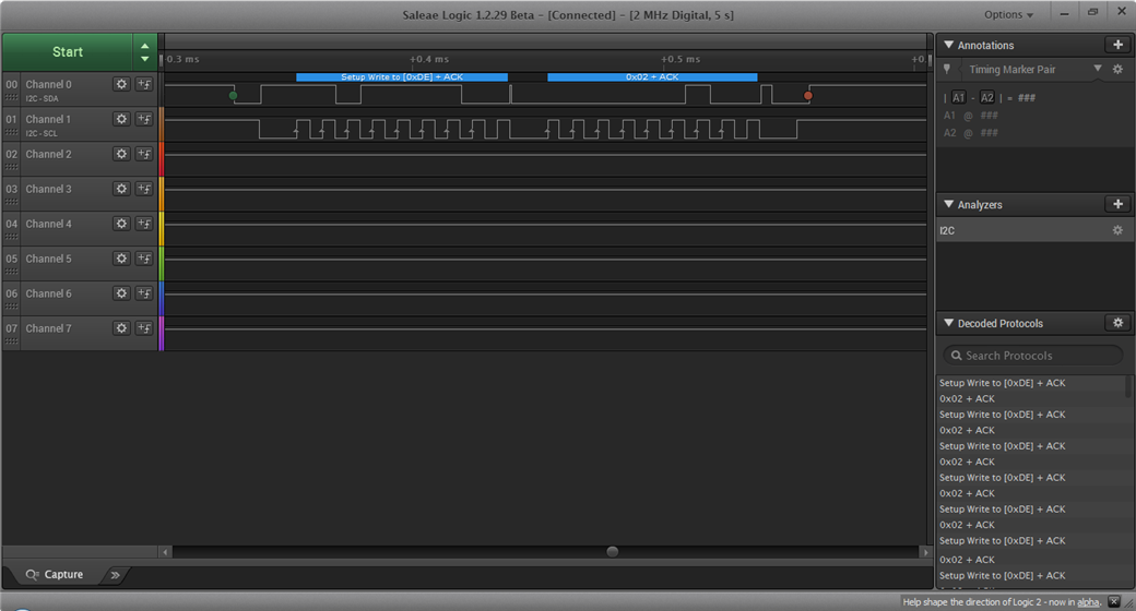
Yes, now you are writing to register with address 0x02 of the device with address 0xDE, but you are not providing the value you want to write to register 0x02.
uint8_t tx_data[] = {REG_RTCHOUR, <value to write to REG_RTCHOUR register> };

err_code = nrf_drv_twi_tx(&m_twi,MCP7940_I2C,tx_data , sizeof(tx_data));

APP_ERROR_CHECK(err_code)
Pls check
const uint8_t  MCP7940_ST                =         7; ///< MCP7940 register bits. RTCSEC reg
//REST variables remains same as above
	while(1)
	{
	uint8_t tx_data[] = {REG_RTCSEC, MCP7940_ST };
	uint8_t rx_data[] = REG_RTCSEC;

	//trying to start oscillator
		err_code = nrf_drv_twi_tx(&m_twi,MCP7940_I2C,tx_data , sizeof(tx_data),false);
		APP_ERROR_CHECK(err_code);
	  err_code = nrf_drv_twi_rx(&m_twi,MCP7940_I2C,rx_data,1);
		nrf_delay_ms(1);
    }
If you want to start the oscillator, then you need to set bit 7 in REG_RTCSEC to 1, i.e. you need to write 0x80 not 0x07.
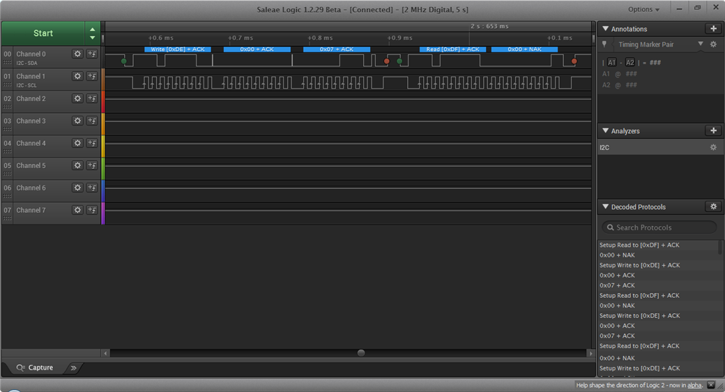
The read operation is Not Acknowledged so it could be that you have to select the register you want to read from before
// Read REG_RTCSEC register
uint8_t tx_data[] = {REG_RTCSEC };
uint8_t rx_data[] = {0};
// Select REG_RTCSEC register and use repeated start
err_code = nrf_drv_twi_tx(&m_twi,MCP7940_I2C,tx_data , sizeof(tx_data),true);
APP_ERROR_CHECK(err_code);
// Read REG_RTCSEC register
err_code = nrf_drv_twi_rx(&m_twi,MCP7940_I2C,rx_data,1);
APP_ERROR_CHECK(err_code);
Please check still NAK

Yes, but you are reading back the value of the register, i.e. 0x07. Wasnt that what you wrote to the register previously? What is the return code of nrf_drv_twi_rx()? Is it NRF_ERROR_DRV_TWI_ERR_DNACK or NRF_ERROR_DRV_TWI_ERR_ANACK?
err_code = 0

Ok, if the nrf_drv_twi_rx call does not return a non-zero error code, then things are working as they should. Could you try to run the following code and see if the rx_data[0] is 0x80. If it is then the code is working as intended.
// Initizalize buffers
uint8_t tx_data[] = {REG_RTCSEC, 0x80 }; // Set TX buffer - Write 0x80 ( Enable Osc) to REG_RTCSEC register
uint8_t rx_data[] = {}; // Empty RX buffer

// Write Tx data to MCP7940
err_code = nrf_drv_twi_tx(&m_twi,MCP7940_I2C,tx_data , sizeof(tx_data),false);
APP_ERROR_CHECK(err_code);

// Select REG_RTCSEC register and use repeated start (only send 1 byte of tx buffer)
err_code = nrf_drv_twi_tx(&m_twi,MCP7940_I2C,tx_data , 1 ,true);
APP_ERROR_CHECK(err_code);

// Read REG_RTCSEC register
err_code = nrf_drv_twi_rx(&m_twi,MCP7940_I2C,rx_data,1);
APP_ERROR_CHECK(err_code);
Best regards
Bjørn