This post is older than 2 years and might not be relevant anymore
More Info: Consider searching for newer posts

GPIO setup parameters for AoA Antenna switching

I have an issue with getting the I/Os correctly setup for antenna switching.

I am running the radio_test example code with the following modifications. 

So far, I have the following code for the GPIO setup:

//Defines are at top of file
#define ANT1 NRF_GPIO_PIN_MAP(0,17)
#define ANT2 NRF_GPIO_PIN_MAP(1,8)
#define ANT3 NRF_GPIO_PIN_MAP(1,7)
#define ANT4 NRF_GPIO_PIN_MAP(1,6)

//other support code

//Pin config
nrf_gpio_pin_clear(ANT1);
nrf_gpio_cfg_output(ANT1);
nrf_gpio_pin_clear(ANT2);
nrf_gpio_cfg_output(ANT2);
nrf_gpio_pin_clear(ANT3);
nrf_gpio_cfg_output(ANT3);
nrf_gpio_pin_clear(ANT4);
nrf_gpio_cfg_output(ANT4);

//DFE pin config
NRF_RADIO->PSEL.DFEGPIO[0] = ANT1; //(P0.17)
NRF_RADIO->PSEL.DFEGPIO[1] = ANT2; //(P1.08)
NRF_RADIO->PSEL.DFEGPIO[2] = ANT3; //(P1.07)
NRF_RADIO->PSEL.DFEGPIO[4] = ANT4; //(P1.06)

NRF_RADIO->SWITCHPATTERN = 1; //Only P0.07 active
NRF_RADIO->SWITCHPATTERN = 2; //Only P1.08 active
NRF_RADIO->SWITCHPATTERN = 4; //Only P1.07 active
NRF_RADIO->SWITCHPATTERN = 8; //Only P1.06 active

NRF_RADIO->DFEMODE = RADIO_DFEMODE_DFEOPMODE_AoA;
NRF_RADIO->DFECTRL1 = 10 << RADIO_DFECTRL1_NUMBEROF8US_Pos | 
                       1 << RADIO_DFECTRL1_DFEINEXTENSION_Pos;

Then in the radio_test.c file, I include in the function radio_rx( ...)

uint32_t g_iq_packet[RADIO_MAX_PAYLOAD_LEN];

void radio_rx(....)
{
//orig example code still exists here, only not shown
    NRF_RADIO->DFEPACKET.PTR = (uint32_t)g_iq_packet;

}

From a board running the radio_test example, I issue the 'start_tx_modulated_carrier' command the immediately issue the 'start_rx" command on a seperate DK also running the radio_test example with the above modifications.

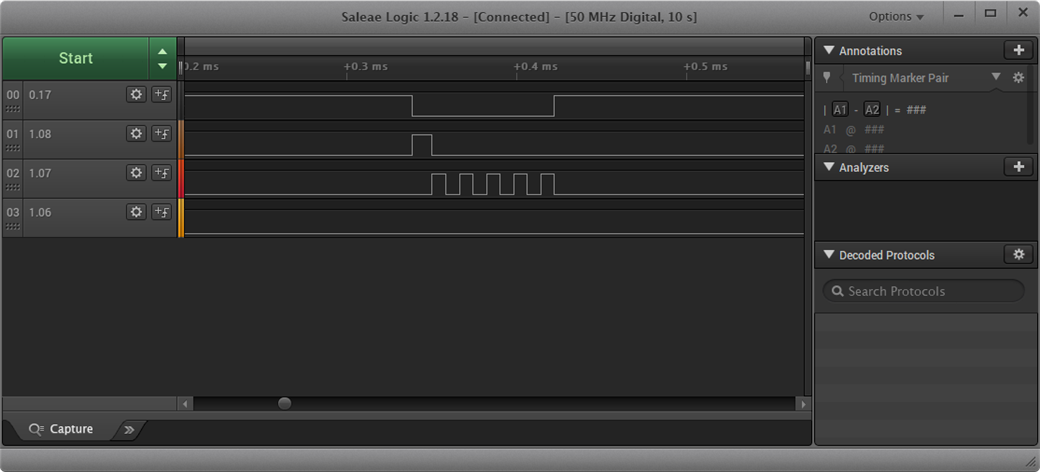
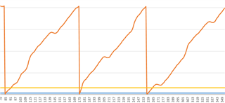
I expected to see a short duration square wave on each of the antenna GPIO pins, so, 4 square waves cascading in time. However from my logic analyzer capture, you can clearly see that is not the case.

How should I be setting up the config registers to fire each of the pins.  Nothing else is connected to the board except the logic analyzer.

Also, how do I correlate the IQ data from the DFEPACKET.PTR to the specific antenna?

Parents
  • A result of some tests:

    I have my configuration as follows:

    NRF_RADIO->DFEMODE = RADIO_DFEMODE_DFEOPMODE_AoA;
    NRF_RADIO->DFECTRL1 = 3 << RADIO_DFECTRL1_NUMBEROF8US_Pos | 
                           1 << RADIO_DFECTRL1_DFEINEXTENSION_Pos |
                           3 << RADIO_DFECTRL1_TSWITCHSPACING_Pos |
                           1 << RADIO_DFECTRL1_TSAMPLESPACINGREF_Pos |
                           3 << RADIO_DFECTRL1_TSAMPLESPACING_Pos ;
    
    
    NRF_RADIO->CTEINLINECONF = 1 << RADIO_CTEINLINECONF_CTEERRORHANDLING_Pos |
                               0 << RADIO_CTEINLINECONF_CTEINFOINS1_Pos;

    Which gives me a response on the RX side as the following:

    Received payload:
    Buffered IQ Samples:14
    Data0: -130, 26624, 
    Data1:  -157, 9216, 
    Data2:  -96, 30208, 
    Data3:  -13, -768, 
    Data4:  1, -2816, 
    Data5:  -117, 29440, 
    Data6:  -11, 17664, 
    Data7: 1, -5376, 
    Data8:  5, -2560, 
    Data9:  -11, 17152,
    Data10: 70, 22016,
    Data11: 12, -4864,
    Data12:  5, -1536, 
    Data13:  54, 19456

    The first number is the I and the second is the Q.  With how I have the RX side configured, my NUMBEROF8US is 3, meaning I have 24uS total. The TSAMPLESPACINGRED is set to 4uS ann my TSAMPLESPACING and TSWITCHSPACING is set to 1uS intervals.

    I dont understand how I am getting 14 IQ samples. If I am getting 2 samples in my REFERENCE period, that would leave 12 samples for IQ. but then that would mean my my total time is  4uS (guard band) + 8uS (reference) + 12uS(Sample time) + 12uS ( Switching time) = 36uS.  

    Can you help shed light?

    Thanks!

  • Are you setting NRF_RADIO->DFEPACKET.MAXCNT  and then checking NRF_RADIO->DFEPACKET.AMOUNT before grabbing the samples?

  • That's more like it. Well spotted Dmitry. Before using multiple antennas you might want to dump your samples into a spreadsheet to confirm that you're getting good data. Here's mine with 0.125us sampling from a 1Mbps CTE :

    (The MagPhase plot is not aligned with IQ plot because the data comes from 2 different runs). I believe the discontinuity at 8us (the end of the reference period) is expected. 

  • Thank you for your suggestion Dmitry, that helped make the data sane.

    From my 4-antenna switching, I am seeing the following:

    if I calculate 1000 * atan(q / i) I get :

    Which is starting to look better, but I am just trying to understand what happens during switching. Any insight on that? ( the 1000 multiplier was merely to get the nrf_cli_fprintf to accept the number as it is natively in floating point and I am doing a dirty conversion to fixed point)

    My settings for this test:

    NRF_RADIO->DFECTRL1 = 3 << RADIO_DFECTRL1_NUMBEROF8US_Pos |
    1 << RADIO_DFECTRL1_DFEINEXTENSION_Pos |
    3 << RADIO_DFECTRL1_TSWITCHSPACING_Pos |
    6 << RADIO_DFECTRL1_TSAMPLESPACINGREF_Pos |
    6 << RADIO_DFECTRL1_TSAMPLESPACING_Pos ;

  • A second half looks like switching results. The distance between points from the same antenna is 16 samples (2us).

    It seems your antenna switch is not very fast. You can look at results from my board with SKY66112:

  • Hi Dmirty,  Can you post your register configs for registers DFEMODE through to DFEPACKET.MAXCNT? I think I am almost there, just need to tweak my settings. Also I am using the SKY13322 dev board.

    Thanks!  

  • Hi,

    here's my DFE configuration: 

    	RADIO->CTEINLINECONF = 0;
    	RADIO->DFECTRL1 = DFELEN8US(64) | DFEINEXT(0) | DFESWITCH_4us | 
    				DFESAMPLEREF_125ns | DFESAMPLE_IQ | DFESAMPLEMAIN_125ns | DFEAGCBACKOFF(0);
    	RADIO->DFECTRL2 = DFESWITCHOFFSET((DATALEN_AoD * 8 + 6) * 16) | DFESAMPLEOFFSET(-208);
    	RADIO->DFEPACKET.PTR = (uint32_t) shared_buffer;
    	RADIO->DFEPACKET.MAXCNT = sizeof(shared_buffer) / sizeof(uint32_t);
    

    DFECTRL1 and DEFCTRL2 are found with trial-and-error method, shared_buffer is currently 4 kbytes.

    I's very strange that transition takes so much time. Did you set high drive mode for switch GPIOs?

Reply
  • Hi,

    here's my DFE configuration: 

    	RADIO->CTEINLINECONF = 0;
    	RADIO->DFECTRL1 = DFELEN8US(64) | DFEINEXT(0) | DFESWITCH_4us | 
    				DFESAMPLEREF_125ns | DFESAMPLE_IQ | DFESAMPLEMAIN_125ns | DFEAGCBACKOFF(0);
    	RADIO->DFECTRL2 = DFESWITCHOFFSET((DATALEN_AoD * 8 + 6) * 16) | DFESAMPLEOFFSET(-208);
    	RADIO->DFEPACKET.PTR = (uint32_t) shared_buffer;
    	RADIO->DFEPACKET.MAXCNT = sizeof(shared_buffer) / sizeof(uint32_t);
    

    DFECTRL1 and DEFCTRL2 are found with trial-and-error method, shared_buffer is currently 4 kbytes.

    I's very strange that transition takes so much time. Did you set high drive mode for switch GPIOs?

Children
Related