This post is older than 2 years and might not be relevant anymore
More Info: Consider searching for newer posts

Adapting examples for NRF52840 dongle PCA10059

Greeting to Nordic Team!

I'm new to nordic devices as well as Q&A section, so apologies in advance if I make any mistakes raising a question.

Two things I would like to discuss:

Intro and adaptions I have made so far:

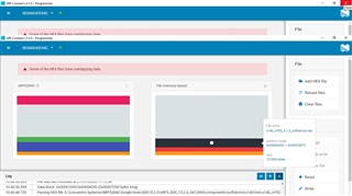
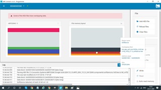
I have got two NRF52840 dongle, but no nrf52DK. I have downloaded and installed nrfConnect, Segger Embedded Studio, and SDK 15.2.0 as well as SDK15.3.0 (I wasn't sure which one I will be needing)I have gone through coule of tutorials fro BLE and Adapting examples for dongle links as follows:

1. https://devzone.nordicsemi.com/nordic/short-range-guides/b/bluetooth-low-energy/posts/ble-advertising-a-beginners-tutorial

2. https://devzone.nordicsemi.com/nordic/short-range-guides/b/bluetooth-low-energy/posts/ble-services-a-beginners-tutorial

3. https://devzone.nordicsemi.com/nordic/short-range-guides/b/bluetooth-low-energy/posts/ble-characteristics-a-beginners-tutorial

and finally for adapting examples for dongle

https://devzone.nordicsemi.com/nordic/short-range-guides/b/getting-started/posts/nrf52840-dongle-programming-tutorial

Example in use: blinky_app

The first problem :

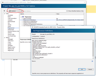
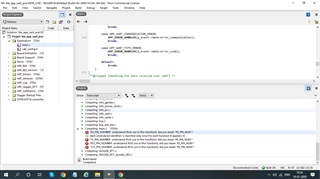
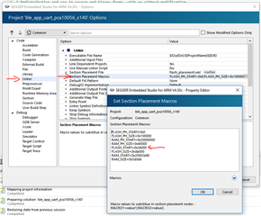
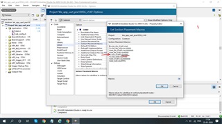
      I faced was as guided in the dongle programming tutorial, I can't see any preprocessor definitions rather the it says "inherit" and when I click three dots besides it, I find the text box complete empty and nothing over there. Do I need to write all of the stuff shown in the tutorial by myself or it appears by itself and I just need to remove the PCA10056 and replace it with PCA10059. If so, why my preprocessor definitions seems empty. same is case with the linker option it says "inherit" and the text box for linker is empty. Please provide an explanation for this.

Also in a thread I read, I need to explicitly undefine the board I'm not using(in this case it would be PCA10056). Link https://devzone.nordicsemi.com/f/nordic-q-a/43760/adapting-the-blinky-example-from-the-nrf52840-dk-to-the-nrf52840-dongle/171455#171455. Do you confirm this? 

The main Issue:

    I wish to create a project on nrf52840 dongle that accepts data from android app and stores it on SD card and later retrive it and send it to the desktop computer, all these is expected to happen over BLE. One of my friend has created an android app which has a form like structure which accepts several information from the user like Name, age, address, nature of complaints, complaints, etc. So far I'm able to connect my NRF52840 dongle with the android app and nothing further than that. Which SDK examples should I refer for my project? Or do I need to write completely different program for my project? as said earlier this my first time working with NRF device previously I have extensively worked with Arduinos and ESPs.

waiting for timely help and valuable guidance. Thanks in advance

Parents
  • Hi,

    If so, why my preprocessor definitions seems empty. same is case with the linker option it says "inherit" and the text box for linker is empty. Please provide an explanation for this.

    The reason you only see "inherit" is that you have not selected the common configuration. "Release" and "Debug" both inherit from "Common", and that is where you should do your changes. Please see this screenshot:

    Also in a thread I read, I need to explicitly undefine the board I'm not using(in this case it would be PCA10056). Link https://devzone.nordicsemi.com/f/nordic-q-a/43760/adapting-the-blinky-example-from-the-nrf52840-dk-to-the-nrf52840-dongle/171455#171455. Do you confirm this? 

    No. There is no need to undefine the other board, just remove the definition in the first place, and add the correct one for the dongle.

    Regarding your application, there are no examples that do this for you, but you can find several relevant examples in the SDK. You can find an SD card example under HW peripheral examples and several relevant BLE peripheral examples. You can also find examples of USB CDC for communication with the computer over USB if that is the intention.

    Please note that I recomend obtaining an nRF52840 DK to do the development since having a debugger is essential when sorting out issues.

    Br,

    Einar

  • I changed the setting to common and then I right click on the project and hit build. I am using ble_app_uart example now. it gave me couple of errors. I am attaching a screenshot of the same. what am I missing now? is uart example not meant to be used with dongle? if so what is the alternate example which would serve the purpose of uart example

  • Hi,

    Chirantan Kansara said:
    Can you assit me in pointing out to any document which explains this in bit more detail I am bit confused about its implementation right now.

    I am not sure exactly where to start other than the examples I pointed to, but you can read more by browsing the Infocenter. Perhaps if you can elaborate on what more you need documentation for?

    Chirantan Kansara said:
    If I define any two pins as UART pins then how it would be possible?

    The UART peripheral on the nRF can use any GPIO's as UART pins. So you just need to define the pins in the same way it is done for other boards, as mentioned in my previous post. Use some pins that are unused and which you can easily access physically.

    Chirantan Kansara said:
    hould I then connect these pins to module like CP2102 and plug that module into the computer?

    Yes, for instance. Alternatively, you can replace the dongle with an nRF52840 DK if possible, as that would be a much better platform to develop on. This has an onboard USB-UART bridge as part of the onboard debugger. (Also, the debugger itself is crucial when debugging embedded code). Another option is to implement UART over USB on the nRF52840 dongle, as demonstrated by the USBD BLE UART Example.

  • I am not sure exactly where to start other than the examples I pointed to, but you can read more by browsing the Infocenter. Perhaps if you can elaborate on what more you need documentation for?

    Like where should I find the PCA10059.h for ble_app_uart. That's the example I will be using to receive the data from my android app right? if so, then I don't see any PCA10059.h file in it then how I am supposed to modify it?

    I have made a custom PCB where my Dongle is supposed to mount on it and I have attached two pins of dongle 0.29 as Rx and 0.31 as Tx and connected them to AVR microcotnroller which inturn is connected to SD card. So would it be possible if use ble_app_uart to receive data from android app via Dongle and pass it to AVR on serial So that my AVR can store it SD card? I can program the AVR. Just let me know if I am on the right track about using ble_app_uart for this purpose. If so, at which baudrate do I need to do this communication with AVR? AVR supports many baudrates but mostly used of them is 9600 can my dongle work on this baudrate?

    awaiting your reply

  • Hi,

    Chirantan Kansara said:
    Like where should I find the PCA10059.h for ble_app_uart. That's the example I will be using to receive the data from my android app right? if so, then I don't see any PCA10059.h file in it then how I am supposed to modify it?

    There is just one pca10059.h in the SDK, and that is located under <SDK>\components\boards\, which is the folder where all board files are located. As is the case with other header files, the file itself is not added to the project, but the folder is in the list of included directories. And the correct board file is seleceted based on the board define (BOARD_PCA10059).

    Chirantan Kansara said:
    I have made a custom PCB where my Dongle is supposed to mount on it and I have attached two pins of dongle 0.29 as Rx and 0.31 as Tx and connected them to AVR microcotnroller which inturn is connected to SD card. So would it be possible if use ble_app_uart to receive data from android app via Dongle and pass it to AVR on serial So that my AVR can store it SD card?

    Yes. Then you should update pca10059.h with these ports as explained before, or you can modify the example to use pins you specify rather than taking them from the board file. If you just add the two defines to your board file and make sure to disable flow control by defining HWFC to false (since you don't have those pins connected), everything should work out of the box.

  • Thanks and I will update with the reply with what happens next

  • Sorry, I got bit lil busy with other projects but I followed all those steps and got it to the point where I need to upload the program to my chip and I got a Waring of overlapping memory locations. I have attached the screenshots of the same. Is it safe to proceed like this? or have done something wrong? Awaiting your kind reply eagerly

Reply Children
  • Hi,

    I see your application starts at 0x1000. This is correct for examples that do not use the SoftDevice since that places the application immediately after the MBR. However, since your application uses the SoftDevice, it should be located immediately after the SoftDevice. If you are adapting an existing example that uses the SoftDevice, that means you should not change the address, since it is already correct. Alternatively, you can check the SoftDevice specification for your exact SoftDevice version, and see the size. The start address of the application is equal to the size of the SoftDevice (including MBR).

  • Hello! thanks for reply!

    I am using s140 softdevice the same which I used while I was burning blinky_app and now I am using ble_app_uart from ble peripheral. Am I going correct I'm using SDK version 15.2.0. I havent changed any memory locations by myself I kept them as it is and just followed the instructions given by you earlier posts. what else do I need to do?

  • Hi,

    Chirantan Kansara said:
    what else do I need to do?

    It is not entirely clear to me what exactly you have done. The nRF52840 Dongle Programming Tutorial explains all the steps in detail, so basically you should follow that.

    As mentioned, it looks to me like you have set the application start address wrong. Can you confirm that it is set to the size of the SoftDevice? Alternatively, can you just show the memory configuration for your project? You find it here:

    Since you are adapting a project that uses a SoftDevice you should just keep these settings as is. In other words, with S140 version 6.1.0, FLASH_START for the application should always be 0x26000.

  • Thanks for the reply!

    Now I am trying to upload ble_app_uart example and I am using S140 softdevice. I have made changes in Preprocessor definitions and linker configuration as mentioned in the tutorial. I changed RX tx and two other pins in boards.hex file of PCA100059 as you advised me in earlier post. Apart from these changes I haven't made any changes to the entire coed or its configuration in any sense.

    I followed the tutorial:

    https://devzone.nordicsemi.com/nordic/short-range-guides/b/getting-started/posts/nrf52840-dongle-programming-tutorial

    and it says I have to edit some definitions in linker as:

    Adjust the linker configuration. Set FLASH_START=0x1000 to place the application right above the MBR. You should also set FLASH_SIZE=0xDF000 to make sure that there is room for the bootloader at the end of the flash. Set RAM_START=0x20000008, as the first 8 bytes are used by the MBR for interrupt forwarding and adjust the size accordingly by setting RAM_SIZE=0x3FFF8.

    I did the same as it says in the tutorial.


    Besides 

    Since you are adapting a project that uses a SoftDevice you should just keep these settings as is. In other words, with S140 version 6.1.0, FLASH_START for the application should always be 0x26000.

    Do I need to make any other changes that differ from the ones that are prescribed in the tutorial mentioned above? If so please let me know in detail.

    Waiting for your reply

  • My apologies the tutorial section says "without Softdevice". I will undo the changes and get back

Related