This post is older than 2 years and might not be relevant anymore
More Info: Consider searching for newer posts

app_uart_get more than 1 byte

Hi,

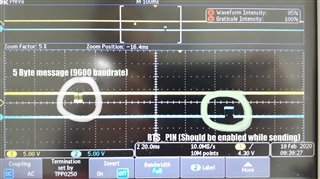
I'm using app_uart for communication between different mcu. I can send more than 1 byte like "0x3917015623"  through  changing tx_buffer[0] to tx_buffer[5]. Unfortunately i couldn't recieve the slave devicess message "0x2917013607". I can only get the first byte "0x07". My configuration are the same as uart example. How can i recieve all the message ?. I tried to use serial library but i couldn't initialize. (It gave ERROR 6 NRF_ERROR_NOT_SUPPORTED).

Slave device is sending me a message every second. And i'm calling app_uart_get function every 500 miliseconds.

Here is my uart init;

Fullscreen
1
2
3
4
5
6
7
8
9
10
11
12
13
14
15
16
17
18
19
20
21
void uart_error_handle(app_uart_evt_t * p_event)
{
if (p_event->evt_type == APP_UART_COMMUNICATION_ERROR)
{
APP_ERROR_HANDLER(p_event->data.error_communication);
}
else if (p_event->evt_type == APP_UART_FIFO_ERROR)
{
APP_ERROR_HANDLER(p_event->data.error_code);
}
}
void uart_init(void)
{
uint32_t err_code;
const app_uart_comm_params_t comm_params =
{
RX_PIN_NUMBER,
TX_PIN_NUMBER,
RTS_PIN_NUMBER,
CTS_PIN_NUMBER,
XXXXXXXXXXXXXXXXXXXXXXXXXXXXXXXXXXXXXXXXXXXXXXXXXX

Regards,

Parents
  • I tried to use serial library but i couldn't initialize. (It gave ERROR 6 NRF_ERROR_NOT_SUPPORTED).

     Which function returned NRF_ERROR_NOT_SUPPORTED?

  • nrf_serial_init function was returning NRF_ERROR_NOT_SUPPORTED. I fixed that error yesterday. I did a lot of things. I couldn't remember exactly but i remember that i changed some code in nrf_serial.c . Now, i can send 5 byte data on TX_PIN  but i received wrong data from slave. Also i am using MAX485 IC for communication. I need to set RTS_PIN before sending operation and clear it before receive operation. But nrf_gpio_pin_set or nrf_gpio_pin_clear command doesn't effect the RTS_PIN. When i deactive UART module then these command are starting to work. When UART module enabled, RTS_PIN goes high at wrong time and out of my control. Time between sending operation and RTS_PIN high is about 95 ms. It should be at the same time. So how can i control RTS pin while UART Module enabled.(I can control other gpio when uart enabled.)

    here is my serial init code:

    Fullscreen
    1
    2
    3
    4
    5
    6
    7
    8
    9
    10
    11
    12
    13
    14
    15
    16
    17
    18
    19
    20
    21
    NRF_SERIAL_DRV_UART_CONFIG_DEF(m_uart0_drv_config,
    RX_PIN_NUMBER, TX_PIN_NUMBER,
    RTS_PIN_NUMBER, CTS_PIN_NUMBER,
    NRF_UART_HWFC_ENABLED, NRF_UART_PARITY_EXCLUDED,
    NRF_UART_BAUDRATE_9600,
    UART_DEFAULT_CONFIG_IRQ_PRIORITY);
    #define SERIAL_FIFO_TX_SIZE 32
    #define SERIAL_FIFO_RX_SIZE 32
    NRF_SERIAL_QUEUES_DEF(serial_queues, SERIAL_FIFO_TX_SIZE, SERIAL_FIFO_RX_SIZE);
    #define SERIAL_BUFF_TX_SIZE 5
    #define SERIAL_BUFF_RX_SIZE 5
    NRF_SERIAL_BUFFERS_DEF(serial_buffs, SERIAL_BUFF_TX_SIZE, SERIAL_BUFF_RX_SIZE);
    NRF_SERIAL_CONFIG_DEF(serial_config, NRF_SERIAL_MODE_IRQ,
    &serial_queues, &serial_buffs, NULL, NULL);
    XXXXXXXXXXXXXXXXXXXXXXXXXXXXXXXXXXXXXXXXXXXXXXXXXX
    Fullscreen
    1
    2
    3
    4
    5
    6
    7
    8
    9
    10
    11
    12
    ret_code_t ret;
    // ret = nrf_drv_clock_init();
    // APP_ERROR_CHECK(ret);
    // ret = nrf_drv_power_init(NULL);
    // APP_ERROR_CHECK(ret);
    nrf_drv_clock_lfclk_request(NULL);
    ret = app_timer_init();
    APP_ERROR_CHECK(ret);
    ret = nrf_serial_init(&serial_uart, &m_uart0_drv_config, &serial_config);
    APP_ERROR_CHECK(ret);
    XXXXXXXXXXXXXXXXXXXXXXXXXXXXXXXXXXXXXXXXXXXXXXXXXX

  • What are you passing as the timeout_ms value when you call nrf_serial_read?

    Fullscreen
    1
    2
    3
    4
    5
    6
    7
    8
    9
    10
    11
    12
    13
    14
    15
    16
    17
    18
    /**
    * @brief Function for reading from a serial port.
    *
    * @param p_serial Serial port instance.
    * @param p_data Receive buffer pointer.
    * @param size Receive buffer size.
    * @param p_read Amount of data actually read from the serial port.
    * NULL pointer can be passed.
    * @param timeout_ms Operation timeout, in milliseconds. Pass 0 to operate in
    * non blocking mode.
    *
    * @return Standard error code.
    * */
    ret_code_t nrf_serial_read(nrf_serial_t const * p_serial,
    void * p_data,
    size_t size,
    size_t * p_read,
    uint32_t timeout_ms);
    XXXXXXXXXXXXXXXXXXXXXXXXXXXXXXXXXXXXXXXXXXXXXXXXXX

  • Fullscreen
    1
    2
    3
    4
    5
    6
    7
    8
    9
    10
    11
    12
    13
    14
    15
    16
    17
    18
    19
    20
    uint32_t err_code;
    err_code = nrf_serial_read(&serial_uart, &rx_message, sizeof(rx_message), NULL, 10);
    NRF_LOG_INFO("Recieved error : %d \n",err_code);
    if(err_code == 13)
    {
    ret = nrf_serial_uninit(&serial_uart);
    APP_ERROR_CHECK(ret);
    nrf_delay_ms(10);
    ret = nrf_serial_init(&serial_uart, &m_uart0_drv_config, &serial_config);
    APP_ERROR_CHECK(ret);
    }
    (void)nrf_serial_flush(&serial_uart, 0);
    if(rx_message[3]>0)
    NRF_LOG_INFO("Recieved data : %d \n", rx_message[3]);
    rx_message[3] = rx_data;
    our_rx_characteristic_update(&m_our_service, &rx_data);
    err_code = 0;
    XXXXXXXXXXXXXXXXXXXXXXXXXXXXXXXXXXXXXXXXXXXXXXXXXX

    I call this function each second. When i connected the Board via BLE, frequency of errors is increasing.

  • Hi Mehmet, 

    the SoftDevice( i.e. BLE protocol stack) has the highest priority so whenever there is a BLE event, then the SoftDevice will preempt any application code, see Interrupt priority levels in the SoftDevice Specification. 

    So the fact that you see timeouts when there is BLE activity is to be expected as the SoftDevice will get priority over the application UART code. It is possible to schedule application code around the BLE events using the Timeslot API, see Concurrent multiprotocol implementation using the Radio Timeslot API

    Best regards

    Bjørn

  • Is there any example of it ? Would you please explain ".It is possible to schedule application code around the BLE events using the Timeslot API "?. Did you mean scheduler ?

  • We have a tutorial on the Timeslot API. Its based on SDK v11, but the Timeslot API has not changed very much since then so it should still be relevant, see https://devzone.nordicsemi.com/nordic/short-range-guides/b/software-development-kit/posts/setting-up-the-timeslot-api

    The Timeslot API allows the application to request a timeslot where you are guaranteed that there will be no interrupts from the SoftDevice. YOu can perform the UART transaction in the Timeslot to avoid the timeout issues. 

Reply Children
  • Well, i will try it. My Development Kit has broken i guess. I created a new ticket for it. Can i program my Custom Board with ST-Link on STM dev kits?

  • I tried timeslot, actually i am not sure that i did it correct. I got  "<error> app: SOFTDEVICE: ASSERTION FAILED" error. The program is falling error after  serial_timslot.h line : 180

    Q1: where shoul i call timeslot_sd_init() ? Is this function start to my receiving operation ? Should i call it in main just one time or every time when i want to read rx pin?

    serial_timslot.h

    Fullscreen
    1
    2
    3
    4
    5
    6
    7
    8
    9
    10
    11
    12
    13
    14
    15
    16
    17
    18
    19
    20
    21
    #include <stdint.h>
    #include <stdbool.h>
    #include "nrf.h"
    #include "app_error.h"
    #include "nrf_gpio.h"
    #include "nrf_sdh.h"
    #include "boards.h"
    #include "nrf_serial.h"
    #include "nrf_drv_uart.h"
    NRF_SERIAL_DRV_UART_CONFIG_DEF(m_uart0_drv_config,
    RX_PIN_NUMBER, TX_PIN_NUMBER,
    RTS_PIN_NUMBER, CTS_PIN_NUMBER,
    NRF_UART_HWFC_DISABLED, NRF_UART_PARITY_EXCLUDED,
    NRF_UART_BAUDRATE_9600,
    UART_DEFAULT_CONFIG_IRQ_PRIORITY);
    XXXXXXXXXXXXXXXXXXXXXXXXXXXXXXXXXXXXXXXXXXXXXXXXXX

    main.c

    Fullscreen
    1
    2
    3
    4
    5
    6
    7
    8
    9
    10
    11
    12
    13
    14
    15
    16
    17
    18
    19
    20
    21
    /**@brief Function for application main entry.
    */
    int main(void)
    {
    ret_code_t rc;
    ret_code_t ret;
    bool erase_bonds;
    // Initialize.
    log_init();
    power_management_init();
    saadc_init();
    timers_init();
    timer_internal_init();
    ble_stack_init();
    gap_params_init();
    gatt_init();
    services_init();
    advertising_init();
    XXXXXXXXXXXXXXXXXXXXXXXXXXXXXXXXXXXXXXXXXXXXXXXXXX

  • HI Mehmet, 

    as stated in step 10 of the tutorial

    1. Add timeslot_sd_init(); to main().

    It should be added after ble_stack_init() so your main() function looks good.  When you call timeslot_sd_init() you should get a NRF_RADIO_CALLBACK_SIGNAL_TYPE_START event indicating that the Timeslot is open and you should get the NRF_RADIO_CALLBACK_SIGNAL_TYPE_TIMER0 event 100us before the slot ends. 

    One change I you will have to do is to add the following line to timeslot.c after the definition of radio_callback. 

    NRF_SDH_SOC_OBSERVER(m_signal_evt_observer, 0, nrf_evt_signal_handler, NULL);

    This replaces step 8 in the tutorial and is needed since we have changed our event dispatch system in the newer SDKs. 

    Best regards

    Bjørn

  • NRF_RADIO_CALLBACK_SIGNAL_TYPE_START event indicating that the Timeslot is open and you should get the NRF_RADIO_CALLBACK_SIGNAL_TYPE_TIMER0 event 100us before the slot ends. 

    Yes, these events occurs.

    It started to work after i removed the breakpoints in radio_callback and also i already added this code in main.c

    Fullscreen
    1
    2
    3
    4
    5
    6
    static void time_slot_soc_evt_handler(uint32_t evt_id, void * p_context)
    {
    (evt_id);
    }
    NRF_SDH_SOC_OBSERVER(m_time_slot_soc_observer, 0, time_slot_soc_evt_handler, NULL);
    XXXXXXXXXXXXXXXXXXXXXXXXXXXXXXXXXXXXXXXXXXXXXXXXXX

    When i started to debug with these changes, i can't receive  data continuously. It just enter timeslot one time. So, i added these codes in main.c line 886.

    Fullscreen
    1
    2
    3
    4
    5
    6
    err_code = request_next_event_earliest();
    if (err_code != NRF_SUCCESS)
    {
    (void)sd_radio_session_close();
    return err_code;
    }
    XXXXXXXXXXXXXXXXXXXXXXXXXXXXXXXXXXXXXXXXXXXXXXXXXX

    Then i can receive data countinuously but only between two nrf. Without timeslot i could receive very less correct data from PIC. With timeslot, nrf to nrf is okey but pic to nrf is not working. I can't receive any correct data with timeslot from PIC. I added my whole main.c below.

    Fullscreen
    1
    2
    3
    4
    5
    6
    7
    8
    9
    10
    11
    12
    13
    14
    15
    16
    17
    18
    19
    20
    21
    #include "Defination.h"
    static void advertising_start(bool erase_bonds);
    /**@brief Function for assert macro callback.
    *
    * @details This function will be called in case of an assert in the SoftDevice.
    *
    * @warning This handler is an example only and does not fit a final product. You need to analyze
    * how your product is supposed to react in case of Assert.
    * @warning On assert from the SoftDevice, the system can only recover on reset.
    *
    * @param[in] line_num Line number of the failing ASSERT call.
    * @param[in] p_file_name File name of the failing ASSERT call.
    */
    void assert_nrf_callback(uint16_t line_num, const uint8_t * p_file_name)
    {
    app_error_handler(DEAD_BEEF, line_num, p_file_name);
    }
    XXXXXXXXXXXXXXXXXXXXXXXXXXXXXXXXXXXXXXXXXXXXXXXXXX

    EDIT : I almost made it, i feel it Smile. Is there any function to check the data on rx_buffer ? I think the received data is 0 when nrf_serial_read function returns error code 13 (NRF_ERROR_TIMEOUT) or  no data on buffer. I just need when data available on UART RX. Here is my output;

    Fullscreen
    1
    2
    3
    4
    5
    6
    7
    8
    9
    10
    11
    12
    13
    14
    15
    16
    17
    18
    19
    20
    21
    <info> app: Recieved data : 1
    <info> app: Recieved data : 0
    <info> app: Recieved data : 2
    <info> app: Recieved data : 3
    <info> app: Recieved data : 4
    <info> app: Recieved data : 0
    <info> app: Recieved data : 5
    <info> app: Recieved data : 6
    <info> app: Recieved data : 0
    <info> app: Recieved data : 7
    <info> app: Recieved data : 8
    XXXXXXXXXXXXXXXXXXXXXXXXXXXXXXXXXXXXXXXXXXXXXXXXXX