Hello,
I'm trying to develop a wearable stacking form-factor where number of boards can be assembled in a deck: MCU, sensors, actuators, power supplies, etc. Size of the boards (cards) is kind of important for wearables, so for the proof of concept I've started with a tiny 20x20 mm PCB and nRF52832 QFN48, samples of which were included into DK and PPK (thanks!).
May I ask you to review the preliminary design of the board prototype, please?
The board has 4 layers, 1.6 mm thick.
Antenna
Of course, the most challenging part is the RF. For such a small PCB with number of other boards beneath it I don't expect it performing high, but there're seem not too many options. I've had a chance to evaluate the Johanson 2450AT42E010BE zero clearance antenna on the board of about the same size (the rayBeacon), and it works. With tiny PCB footprint it looks like a clear winner among other possible options. On the dark side, it's tricky to tune and still suffer from narrow band due to very little ground area.
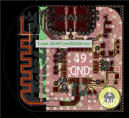
For the first prototype it might be reasonable to start with a printed antenna which I could tune by myself. One option is a monopole trace like that one on the nRF51 smart beacon. However, I've decided to go the harder way and adopted the well known MIFA. As far as I understood how it works, the inductance part of the F antenna is conveniently fixed parallel to the ground plane and seem requires no tuning, and the meandered trace can be easily cut to match the impedance. It's length is 35mm as shown on the picture below. Please also note, there is also one series component.

The antenna questions:
- Which one of the three is better - zero clearance chip antenna, monopole trace, the MIFA? Please note, the chip antenna means substantially bigger ground plane.
- Any advantages to keep the series component for the trace antenna, or can it be safely dropped?
- Should the board size of 20x20 mm be considered as too small for the radio? How much will it help if the board size will be increased to 24x24 mm?
- The very end of the meandered trace miss the complimentary ground plane on the top side. Is it an issue?
Of course, any other notes will be appreciated.
Other traces
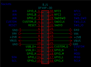
On the north of the board there are the two Hirose DF40 connectors. Placed on the top and on the bottom sides and linked each other, they're used to attach series of similar boards into a deck and act like a bus. Here is the pinout:

First concern is the NFC. The NFC traces are routed to the pins 29 and 30. Main idea about them is to have a dedicated board for the antenna. It was also planned to put tuning capacitors to the antenna board too. Unfortunately, the traces are walking over SWD traces, in particular SWDCLK and SWDIO. Passing NFC from board to board is also not the best idea either. But what do you think?
Another question is about the pins 40 to 43. Accordingly to the board design the pins must be reserved for SPI. But per section 4.3 GPIO Usage Restrictions they must be low frequency I/O. The nRF52832 doesn't support high-speed SPI, but should I be concerned about using the pins for 8MHz SPI?
Generally speaking, I'm not too happy about the "beard" from those vias around the DF40 - just trying to avoid HDI and keep fabrication cost low. Maybe there is something that I've missed about the connectors, and which terribly breaks the design?
I've attached design files. The silklayer is useless, but the *Fab files have all components and values referenced.
Thank you!
Mishka
