This post is older than 2 years and might not be relevant anymore
More Info: Consider searching for newer posts

NRF52840 DK SAADC PIN A0 Reading

Hi All,

I am trying to use the saadc example given in nRF5_SDK_17.0.0_9d13099\examples\peripheral\saadc.

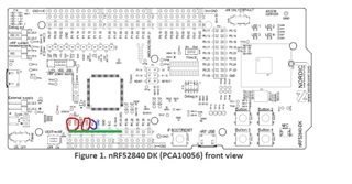
I have built the project and now I want to read some values from some voltages from one of the output pins in nRF52840 DK.

As suggested https://infocenter.nordicsemi.com/topic/com.nordic.infocenter.sdk5.v15.0.0/nrf_dev_saadc_example.html

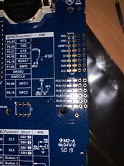
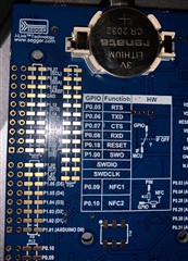
(**To use VCC. In the hardware I see only VDD pins. Is it the same?)  in  

I tried to connect A0 pin to VDD (There are three VDD) pins however, value I read is,

<info> app: SAADC HAL simple example started.
<info> app: ADC event number: 0
<info> app: 19
<info> app: 19
<info> app: 18
<info> app: 19
<info> app: 17

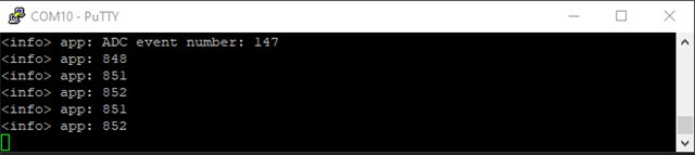
However, if I connect to the 5V pin, I read,


<info> app: ADC event number: 22
<info> app: 559
<info> app: 560
<info> app: 559
<info> app: 560
<info> app: 559

Is it possible to know, why there is no output from the VDD pins? What is the expected voltage output of this pin?

Should I configure anything in the hardware?

Also is it ok to connect the 5V pin to the A0 pin?

Thanks a lot!!

Parents Reply Children
  • See Mapping of analog pins.

    AIN0 is the p0.02 pin on the opposite side of the DK. 

  • Hi, 

    Thanks for the reply. I have few more questions to clarify.

    1. The confusion happened because in my board it is printed as P0.03 (A0). Please see the attached images. So I thought NRF_SAADC_INPUT_AIN0 is for P0.03. In the other side of the board I see P0.02 (AREF). Is this the Pin for the channel NRF_SAADC_INPUT_AIN0? However AIN0 is not mentioned in the pin mapping table.

    2. If I define NRF_SAADC_INPUT_AIN0 as the channel, does it mean the ADC samples only from P0.02? Because initially I used P0.03 with the 5V, the reading was a low value than ~850. Maybe since it wasn't sampling from P0.03, it did not cause any damage. With AIN1 defined I still get a valid reading from P0.03 now.

    3. I observed that when I used NRF_SAADC_INPUT_AIN2 with P0.04, I get a larger fluctuation in the reading when nothing is connected to the pin P0.04. 

    <info> app: ADC event number: 141
    <info> app: -14
    <info> app: -6
    <info> app: -2
    <info> app: -18
    <info> app: -19
    <info> app: ADC event number: 142
    <info> app: 51
    <info> app: 289
    <info> app: 517
    <info> app: 736
    <info> app: 859

    However, if I connect to VDD or GND it measures the correct values. Is this normal?

    Thanks a lot!!

    1. See aQFN73 ball assignments for the MCU. 

    2. "Maybe since it wasn't sampling from P0.03, it did not cause any damage." 
      It's the ESD protection diodes on the pins that are likely to be damaged, they are always present no matter the state the MCU is in. 

      "With AIN1 defined I still get a valid reading from P0.03 now." 
      Then you're lucky. The ESD diodes can handle a tiny current for a very short time before they blow, they are likely degraded, but still functional. 

    3. If it's a floating pin with long traces then it's likely that you're capacitively coupled to other current sources. It depends on the routing of the trace. 
Related