This post is older than 2 years and might not be relevant anymore
More Info: Consider searching for newer posts

Custom waveform generation in two pins

Hello,

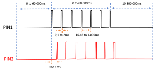
Considering the waveforms in the following chart, which will be the best approach to keep the power consumption as low as possible?

Specifically, which peripheral is suggested (i.e. pwm, timer, ppi)?

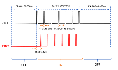
The two (2) waveform are identical, except for the delay between (0 to 2ms).

Thanks
  • Hi,

    the most power-saving approach is an RTC peripheral that would control two GPIOTE channels via PPI.

  • If the waveform is more or less static and don't require higher accuracy than 30.51µs, the RTC + GPIOTE is the best choice. 

    If the waveform is constantly changing and you have strict timing requirements the PWM peripheral will be best.

    Can you share more information on the nature of your signals? 

  • thanks for your feedback and details about the accuracy.

    The application is OK with the accuracy you mentioned (30.51us), considering that will be a considerable saving in power.

    The waveform is fixed, once the parameters are decided, the waveform will be same until new parameters are changed. There are six (6) parameters that we need to adjust, as show the picture below (P1, P2, ..., P6).

    Please, may you give me your suggestion about the setup (for example) of the following static waveform with the RTC + GPIOTE ?

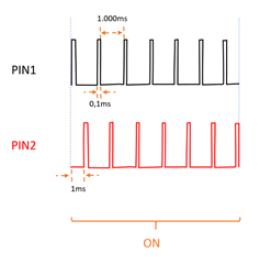
    This waveform (PIN1) have a pulse of 100us with a period of 1000ms. Additionally, have same waveform with a delay of 1ms in other pin (PIN2).

    Thanks

  • The RTC runs on a 32.768kHz clock, which gives it a resolution of 31.5µs. A single RTC only has 4 COMPARE events, this means that you will most likely need to reconfigure the RTC on each state change (OFF -> ON ->OFF...) and that will reduce the time accuracy depending on your implementation. 

    I believe you can generate one period of PIN1/PIN2 with 4 COMPARE events and loop that over and over again, but you will have to track how many periods have passed and re-configure the RTC to the "OFF" state when enough periods have passed.

    Each RTC COMPARE event can be connected to a GPIOTE task, (PIN LoToHi, HiToLo, or Toggle). I suggest you use one toggle task for each pin. 

    f.ex:
    one period of 1000ms = 1s / 1 / 32.768kHz = 32768 cycles. 

    COMPARE[0] = 0.1ms / 30.51µs = ~3 cycles. //toggle PIN1

    COMPARE[1] = 1ms / 30.51µs = ~33 cycles. //toggle PIN2

    COMPARE[2] = 33 + 3 cycles = 36 cycles. //toggle PIN2

    COMPARE[3] = 32768 cycles. //toggle PIN1, clear RTC

    This will run through one period, you then need to let it run for x periods and then stop the RTC and reconfigure it for the "OFF" state. 

Related