This post is older than 2 years and might not be relevant anymore
More Info: Consider searching for newer posts

Custom waveform generation in two pins

Hello,

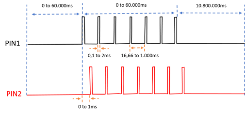
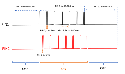
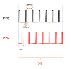
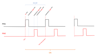
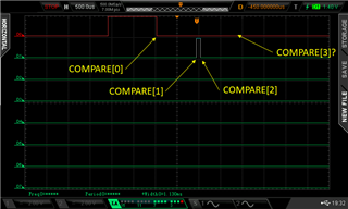
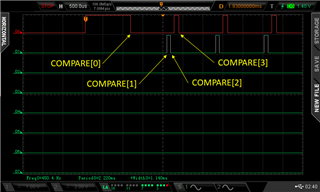
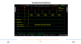
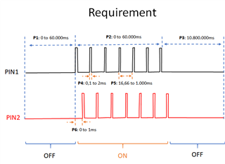
Considering the waveforms in the following chart, which will be the best approach to keep the power consumption as low as possible?

Specifically, which peripheral is suggested (i.e. pwm, timer, ppi)?

The two (2) waveform are identical, except for the delay between (0 to 2ms).

Thanks

Parents
  • Hi,

    the most power-saving approach is an RTC peripheral that would control two GPIOTE channels via PPI.

  • If the waveform is more or less static and don't require higher accuracy than 30.51µs, the RTC + GPIOTE is the best choice. 

    If the waveform is constantly changing and you have strict timing requirements the PWM peripheral will be best.

    Can you share more information on the nature of your signals? 

  • thanks for your feedback and details about the accuracy.

    The application is OK with the accuracy you mentioned (30.51us), considering that will be a considerable saving in power.

    The waveform is fixed, once the parameters are decided, the waveform will be same until new parameters are changed. There are six (6) parameters that we need to adjust, as show the picture below (P1, P2, ..., P6).

    Please, may you give me your suggestion about the setup (for example) of the following static waveform with the RTC + GPIOTE ?

    This waveform (PIN1) have a pulse of 100us with a period of 1000ms. Additionally, have same waveform with a delay of 1ms in other pin (PIN2).

    Thanks

  • The RTC runs on a 32.768kHz clock, which gives it a resolution of 31.5µs. A single RTC only has 4 COMPARE events, this means that you will most likely need to reconfigure the RTC on each state change (OFF -> ON ->OFF...) and that will reduce the time accuracy depending on your implementation. 

    I believe you can generate one period of PIN1/PIN2 with 4 COMPARE events and loop that over and over again, but you will have to track how many periods have passed and re-configure the RTC to the "OFF" state when enough periods have passed.

    Each RTC COMPARE event can be connected to a GPIOTE task, (PIN LoToHi, HiToLo, or Toggle). I suggest you use one toggle task for each pin. 

    f.ex:
    one period of 1000ms = 1s / 1 / 32.768kHz = 32768 cycles. 

    COMPARE[0] = 0.1ms / 30.51µs = ~3 cycles. //toggle PIN1

    COMPARE[1] = 1ms / 30.51µs = ~33 cycles. //toggle PIN2

    COMPARE[2] = 33 + 3 cycles = 36 cycles. //toggle PIN2

    COMPARE[3] = 32768 cycles. //toggle PIN1, clear RTC

    This will run through one period, you then need to let it run for x periods and then stop the RTC and reconfigure it for the "OFF" state. 

  • Thanks for your detailed proposal. 

    Looking at the PPI, RTC and GPIOTE examples I arrived to the following code, in order to implement your suggestions.

    #include "nrf.h"
    #include "nrf_gpio.h"
    #include "nrf_drv_rtc.h"
    #include "nrf_drv_clock.h"
    #include "boards.h"
    #include "app_error.h"
    #include "nrf_drv_ppi.h"
    #include "nrf_drv_gpiote.h"
    #include <stdint.h>
    #include <stdbool.h>
    
    #define GPIO_OUTPUT_PIN1 NRF_GPIO_PIN_MAP(0,27)
    #define GPIO_OUTPUT_PIN2 NRF_GPIO_PIN_MAP(0,26)
    
    const nrf_drv_rtc_t rtc = NRF_DRV_RTC_INSTANCE(0);
    
    void rtc_dummy_handler(nrfx_rtc_int_type_t int_type)
    {
        if (int_type == NRF_DRV_RTC_INT_COMPARE0)
        {
        	;
        }
        else if (int_type == NRF_DRV_RTC_INT_TICK)
        {
        	;
        }
    }
    
    /** @brief Function configuring gpio for pin toggling.
     */
    static void leds_config(void)
    {
        bsp_board_init(BSP_INIT_LEDS);
    }
    
    /** @brief Function starting the internal LFCLK XTAL oscillator.
     */
    static void lfclk_config(void)
    {
        ret_code_t err_code = nrf_drv_clock_init();
        APP_ERROR_CHECK(err_code);
    
        nrf_drv_clock_lfclk_request(NULL);
    }
    
    /** @brief Function initialization and configuration of RTC driver instance.
     */
    static void rtc_config(void)
    {
        uint32_t err_code;
    
        //Initialize RTC instance
        nrf_drv_rtc_config_t config = NRF_DRV_RTC_DEFAULT_CONFIG;
        config.prescaler = 0;
        err_code = nrf_drv_rtc_init(&rtc, &config, rtc_dummy_handler);
        APP_ERROR_CHECK(err_code);
    }
    
    static void waveform_setup()
    {
        uint32_t compare_evt_addr0;
        uint32_t compare_evt_addr1;
        uint32_t compare_evt_addr2;
        uint32_t compare_evt_addr3;
        uint32_t clear_task_addr3;
        uint32_t gpiote_task_addr0;
        uint32_t gpiote_task_addr1;
        uint32_t gpiote_task_addr2;
        uint32_t gpiote_task_addr3;
        uint32_t gpiote_task_addr3a;
        nrf_ppi_channel_t ppi_channel0;
        nrf_ppi_channel_t ppi_channel1;
        nrf_ppi_channel_t ppi_channel2;
        nrf_ppi_channel_t ppi_channel3;
        ret_code_t err_code;


        nrf_drv_gpiote_out_config_t config1 = GPIOTE_CONFIG_OUT_TASK_TOGGLE(true);
        nrf_drv_gpiote_out_config_t config2 = GPIOTE_CONFIG_OUT_TASK_TOGGLE(false);
    
        err_code = nrf_drv_gpiote_out_init(GPIO_OUTPUT_PIN1, &config1);
        APP_ERROR_CHECK(err_code);
        err_code = nrf_drv_gpiote_out_init(GPIO_OUTPUT_PIN2, &config2);
        APP_ERROR_CHECK(err_code);
    
        nrfx_rtc_cc_set(&rtc, 0, 3, false);
        nrfx_rtc_cc_set(&rtc, 1, 33, false);
        nrfx_rtc_cc_set(&rtc, 2, 36, false);
        nrfx_rtc_cc_set(&rtc, 3, 69, false);
    
        err_code = nrf_drv_ppi_channel_alloc(&ppi_channel0);
        APP_ERROR_CHECK(err_code);
        err_code = nrf_drv_ppi_channel_alloc(&ppi_channel1);
        APP_ERROR_CHECK(err_code);
        err_code = nrf_drv_ppi_channel_alloc(&ppi_channel2);
        APP_ERROR_CHECK(err_code);
        err_code = nrf_drv_ppi_channel_alloc(&ppi_channel3);
        APP_ERROR_CHECK(err_code);
    
    
        compare_evt_addr0 = nrf_drv_rtc_event_address_get(&rtc, NRF_RTC_EVENT_COMPARE_0);
        gpiote_task_addr0 = nrf_drv_gpiote_out_task_addr_get(GPIO_OUTPUT_PIN1);
    
        compare_evt_addr1 = nrf_drv_rtc_event_address_get(&rtc, NRF_RTC_EVENT_COMPARE_1);
        gpiote_task_addr1 = nrf_drv_gpiote_out_task_addr_get(GPIO_OUTPUT_PIN2);
    
        compare_evt_addr2 = nrf_drv_rtc_event_address_get(&rtc, NRF_RTC_EVENT_COMPARE_2);
        gpiote_task_addr2 = nrf_drv_gpiote_out_task_addr_get(GPIO_OUTPUT_PIN2);
    
        compare_evt_addr3 = nrf_drv_rtc_event_address_get(&rtc, NRF_RTC_EVENT_COMPARE_3);
        gpiote_task_addr3 = nrf_drv_gpiote_out_task_addr_get(GPIO_OUTPUT_PIN1);
        clear_task_addr3 = nrf_drv_rtc_task_address_get(&rtc, NRF_RTC_TASK_CLEAR);
    
        err_code = nrf_drv_ppi_channel_assign(ppi_channel0, compare_evt_addr0, gpiote_task_addr0);
        APP_ERROR_CHECK(err_code);
        err_code = nrf_drv_ppi_channel_assign(ppi_channel1, compare_evt_addr1, gpiote_task_addr1);
        APP_ERROR_CHECK(err_code);
        err_code = nrf_drv_ppi_channel_assign(ppi_channel2, compare_evt_addr2, gpiote_task_addr2);
        APP_ERROR_CHECK(err_code);
        err_code = nrf_drv_ppi_channel_assign(ppi_channel3, compare_evt_addr3, gpiote_task_addr3);
        APP_ERROR_CHECK(err_code);
        err_code = nrf_drv_ppi_channel_fork_assign(ppi_channel3, clear_task_addr3);
        APP_ERROR_CHECK(err_code);
    
        err_code = nrf_drv_ppi_channel_enable(ppi_channel0);
        APP_ERROR_CHECK(err_code);
        err_code = nrf_drv_ppi_channel_enable(ppi_channel1);
        APP_ERROR_CHECK(err_code);
        err_code = nrf_drv_ppi_channel_enable(ppi_channel2);
        APP_ERROR_CHECK(err_code);
        err_code = nrf_drv_ppi_channel_enable(ppi_channel3);
        APP_ERROR_CHECK(err_code);
    
        nrf_drv_gpiote_out_task_enable(GPIO_OUTPUT_PIN1);
        nrf_drv_gpiote_out_task_enable(GPIO_OUTPUT_PIN2);
    
        nrf_gpio_pin_set(GPIO_OUTPUT_PIN1);
        nrf_gpio_pin_clear(GPIO_OUTPUT_PIN2);
    }
    
    
    /**
     * @brief Function for application main entry.
     */
    int main(void)
    {
        ret_code_t err_code;
    
        err_code = nrf_drv_ppi_init();
        APP_ERROR_CHECK(err_code);
    
        err_code = nrf_drv_gpiote_init();
        APP_ERROR_CHECK(err_code);
    
        lfclk_config();
    
        rtc_config();
    
        waveform_setup();
    
        nrf_drv_rtc_enable(&rtc);
    
        while (true)
        {
            __SEV();
            __WFE();
            __WFE();
        }
    }

    If understand your proposal, it will be similar to below diagram:

    For testing purposes, I set the last compare (COMPARE[3]) to 69 cycles

    The results shows the PIN2 changes as expected, just after 1000ms after the change of PIN1. However, the PIN1 is not changing after 69 cycles. 

    I have a some questions:

    • The source code is implementing your suggestion correctly?
    • When you mentioned that I need to check the number of periods before stop the RTC, how you would suggest that I could check that? Will imply the CPU on on that period?
    • The source code (above) include a compare event task in COMPARE_3 with a clear task. The results shows the pulses only one time. The PIN1 is not changing high when COMPARE[3] pass.

    Thanks

    edit: I updated the chart to match the suggestion from

  • I suggest you use the Toggle task with a single GPIOTE channel for each PIN, instead of the Set and Clear tasks with two channels per pin. 

    You can set the initial condition of the GPIOTE pin so that you don't have to set it manually with the CPU. See nrfx_gpiote_out_config_t and init_state


    Hu Lao said:
    When you mentioned that I need to check the number of periods before stop the RTC, how you would suggest that I could check that? Will imply the CPU on on that period?

    Either you count the number of times the RTC COMPARE[2] interrupt is fired with the CPU, or you can Fork the COMPARE[2] event to a TIMER's COUNT task. If that TIMER is configured as a COUNTER each COMPARE[2] event will increment that TIMER. You can then set up a COMPARE event in that TIMER to f.ex trigger the RTC's STOP task. That way you've automated the process of controlling how many periods you're outputting by setting the TIMER's COMPARE value. 

    A PPI Fork is the ability of a PPI channel to trigger a second TASK. See nrfx_ppi_channel_fork_assign

    Also, what SDK version are you using? 

  • As you suggested, I'm using a Toggle task with single GPIOTE channel for each PIN. Sorry about the diagram, it's doesn't match your suggestion.

    I also set the initial conditions of the GPIOTE with function nrf_drv_gpiote_out_init, specifically as show below

        nrf_drv_gpiote_out_config_t config1 = GPIOTE_CONFIG_OUT_TASK_TOGGLE(true);
        nrf_drv_gpiote_out_config_t config2 = GPIOTE_CONFIG_OUT_TASK_TOGGLE(false);
    
        err_code = nrf_drv_gpiote_out_init(GPIO_OUTPUT_PIN1, &config1);
        APP_ERROR_CHECK(err_code);
        
        err_code = nrf_drv_gpiote_out_init(GPIO_OUTPUT_PIN2, &config2);
        APP_ERROR_CHECK(err_code);

    In this case, how can I set the first pulse (in PIN1) with the correct width?

    Thanks for clarifying the approach suggested to count the cycles. It's clear.

    Currently, the COMPARE[0], COMPARE[1] and COMPARE[2] are toggling the PIN1 and PIN2 as expected, except for the following:

    • The initial pulse width in PIN1 is not correct
    • The COMPARE[3] is not toggling the PIN1
    • The COMPARE[3] is not clearing the RTC. If I change the task from COMPARE[3] to COMPARE[2] event, the RTC is clear.

    Below the waveform acquired

    And source code (modified version of rtc_pca10056)

    #include "nrf.h"
    #include "nrf_gpio.h"
    #include "nrf_drv_rtc.h"
    #include "nrf_drv_clock.h"
    #include "boards.h"
    #include "app_error.h"
    #include "nrf_drv_ppi.h"
    #include "nrf_drv_gpiote.h"
    #include <stdint.h>
    #include <stdbool.h>
    
    #define GPIO_OUTPUT_PIN1 NRF_GPIO_PIN_MAP(0,27)
    #define GPIO_OUTPUT_PIN2 NRF_GPIO_PIN_MAP(0,26)
    
    const nrf_drv_rtc_t rtc = NRF_DRV_RTC_INSTANCE(0);
    
    void rtc_dummy_handler(nrfx_rtc_int_type_t int_type)
    {
        if (int_type == NRF_DRV_RTC_INT_COMPARE0)
        {
        	;
        }
        else if (int_type == NRF_DRV_RTC_INT_TICK)
        {
        	;
        }
    }
    
    /** @brief Function configuring gpio for pin toggling.
     */
    static void leds_config(void)
    {
        bsp_board_init(BSP_INIT_LEDS);
    }
    
    /** @brief Function starting the internal LFCLK XTAL oscillator.
     */
    static void lfclk_config(void)
    {
        ret_code_t err_code = nrf_drv_clock_init();
        APP_ERROR_CHECK(err_code);
    
        nrf_drv_clock_lfclk_request(NULL);
    }
    
    /** @brief Function initialization and configuration of RTC driver instance.
     */
    static void rtc_config(void)
    {
        uint32_t err_code;
    
        //Initialize RTC instance
        nrf_drv_rtc_config_t config = NRF_DRV_RTC_DEFAULT_CONFIG;
        config.prescaler = 0;
        err_code = nrf_drv_rtc_init(&rtc, &config, rtc_dummy_handler);
        APP_ERROR_CHECK(err_code);
    }
    
    static void waveform_setup()
    {
        uint32_t compare_evt_addr0;
        uint32_t compare_evt_addr1;
        uint32_t compare_evt_addr2;
        uint32_t compare_evt_addr3;
        uint32_t clear_task_addr3;
        uint32_t gpiote_task_addr0;
        uint32_t gpiote_task_addr1;
        uint32_t gpiote_task_addr2;
        uint32_t gpiote_task_addr3;
        uint32_t gpiote_task_addr3a;
        nrf_ppi_channel_t ppi_channel0;
        nrf_ppi_channel_t ppi_channel1;
        nrf_ppi_channel_t ppi_channel2;
        nrf_ppi_channel_t ppi_channel3;
        nrf_ppi_channel_t ppi_channel4;
        ret_code_t err_code;
    
        nrf_drv_gpiote_out_config_t config1 = GPIOTE_CONFIG_OUT_TASK_TOGGLE(true);
        nrf_drv_gpiote_out_config_t config2 = GPIOTE_CONFIG_OUT_TASK_TOGGLE(false);
    
        err_code = nrf_drv_gpiote_out_init(GPIO_OUTPUT_PIN1, &config1);
        APP_ERROR_CHECK(err_code);
        err_code = nrf_drv_gpiote_out_init(GPIO_OUTPUT_PIN2, &config2);
        APP_ERROR_CHECK(err_code);
    
        err_code = nrfx_rtc_cc_set(&rtc, 0, 3, false);
        APP_ERROR_CHECK(err_code);
        err_code = nrfx_rtc_cc_set(&rtc, 1, 33, false);
        APP_ERROR_CHECK(err_code);
        err_code = nrfx_rtc_cc_set(&rtc, 2, 36, false);
        APP_ERROR_CHECK(err_code);
        err_code = nrfx_rtc_cc_set(&rtc, 3, 69, false);
        APP_ERROR_CHECK(err_code);
    
        err_code = nrf_drv_ppi_channel_alloc(&ppi_channel0);
        APP_ERROR_CHECK(err_code);
        err_code = nrf_drv_ppi_channel_alloc(&ppi_channel1);
        APP_ERROR_CHECK(err_code);
        err_code = nrf_drv_ppi_channel_alloc(&ppi_channel2);
        APP_ERROR_CHECK(err_code);
        err_code = nrf_drv_ppi_channel_alloc(&ppi_channel3);
        APP_ERROR_CHECK(err_code);
        err_code = nrf_drv_ppi_channel_alloc(&ppi_channel4);
        APP_ERROR_CHECK(err_code);
    
        compare_evt_addr0 = nrf_drv_rtc_event_address_get(&rtc, NRF_RTC_EVENT_COMPARE_0);
        compare_evt_addr1 = nrf_drv_rtc_event_address_get(&rtc, NRF_RTC_EVENT_COMPARE_1);
        compare_evt_addr2 = nrf_drv_rtc_event_address_get(&rtc, NRF_RTC_EVENT_COMPARE_2);
        compare_evt_addr3 = nrf_drv_rtc_event_address_get(&rtc, NRF_RTC_EVENT_COMPARE_3);
    
        gpiote_task_addr0 = nrf_drv_gpiote_out_task_addr_get(GPIO_OUTPUT_PIN1); // PIN1: edge UP 
        gpiote_task_addr1 = nrf_drv_gpiote_out_task_addr_get(GPIO_OUTPUT_PIN2); // PIN2: edge UP 
        gpiote_task_addr2 = nrf_drv_gpiote_out_task_addr_get(GPIO_OUTPUT_PIN2); // PIN2: edge DOWN
        gpiote_task_addr3 = nrf_drv_gpiote_out_task_addr_get(GPIO_OUTPUT_PIN1); // PIN1: edge DOWN 
        clear_task_addr3 = nrf_drv_rtc_task_address_get(&rtc, NRF_RTC_TASK_CLEAR); // RTC: clear counter
    
        err_code = nrf_drv_ppi_channel_assign(ppi_channel0, compare_evt_addr0, gpiote_task_addr0);
        APP_ERROR_CHECK(err_code);
        err_code = nrf_drv_ppi_channel_assign(ppi_channel1, compare_evt_addr1, gpiote_task_addr1);
        APP_ERROR_CHECK(err_code);
        err_code = nrf_drv_ppi_channel_assign(ppi_channel2, compare_evt_addr2, gpiote_task_addr2);
        APP_ERROR_CHECK(err_code);
        err_code = nrf_drv_ppi_channel_assign(ppi_channel3, compare_evt_addr3, gpiote_task_addr3);
        APP_ERROR_CHECK(err_code);
        err_code = nrf_drv_ppi_channel_assign(ppi_channel4, compare_evt_addr3, clear_task_addr3);
        APP_ERROR_CHECK(err_code);
    
        err_code = nrf_drv_ppi_channel_enable(ppi_channel0);
        APP_ERROR_CHECK(err_code);
        err_code = nrf_drv_ppi_channel_enable(ppi_channel1);
        APP_ERROR_CHECK(err_code);
        err_code = nrf_drv_ppi_channel_enable(ppi_channel2);
        APP_ERROR_CHECK(err_code);
        err_code = nrf_drv_ppi_channel_enable(ppi_channel3);
        APP_ERROR_CHECK(err_code);
        err_code = nrf_drv_ppi_channel_enable(ppi_channel4);
        APP_ERROR_CHECK(err_code);
    
        nrf_drv_gpiote_out_task_enable(GPIO_OUTPUT_PIN1);
        nrf_drv_gpiote_out_task_enable(GPIO_OUTPUT_PIN2);
    
        nrf_gpio_pin_clear(GPIO_OUTPUT_PIN1);
        nrf_gpio_pin_clear(GPIO_OUTPUT_PIN2);
    }
    
    
    /**
     * @brief Function for application main entry.
     */
    int main(void)
    {
        ret_code_t err_code;
    
        err_code = nrf_drv_ppi_init();
        APP_ERROR_CHECK(err_code);
    
        err_code = nrf_drv_gpiote_init();
        APP_ERROR_CHECK(err_code);
    
        lfclk_config();
    
        rtc_config();
    
        waveform_setup();
    
        nrf_drv_rtc_enable(&rtc);
    
        while (true)
        {
            __SEV();
            __WFE();
            __WFE();
        }
    }
    

    I'm using nRF5_SDK_17.0.0_9d13099 and a nRF52840 DK for this task.

Reply
  • As you suggested, I'm using a Toggle task with single GPIOTE channel for each PIN. Sorry about the diagram, it's doesn't match your suggestion.

    I also set the initial conditions of the GPIOTE with function nrf_drv_gpiote_out_init, specifically as show below

        nrf_drv_gpiote_out_config_t config1 = GPIOTE_CONFIG_OUT_TASK_TOGGLE(true);
        nrf_drv_gpiote_out_config_t config2 = GPIOTE_CONFIG_OUT_TASK_TOGGLE(false);
    
        err_code = nrf_drv_gpiote_out_init(GPIO_OUTPUT_PIN1, &config1);
        APP_ERROR_CHECK(err_code);
        
        err_code = nrf_drv_gpiote_out_init(GPIO_OUTPUT_PIN2, &config2);
        APP_ERROR_CHECK(err_code);

    In this case, how can I set the first pulse (in PIN1) with the correct width?

    Thanks for clarifying the approach suggested to count the cycles. It's clear.

    Currently, the COMPARE[0], COMPARE[1] and COMPARE[2] are toggling the PIN1 and PIN2 as expected, except for the following:

    • The initial pulse width in PIN1 is not correct
    • The COMPARE[3] is not toggling the PIN1
    • The COMPARE[3] is not clearing the RTC. If I change the task from COMPARE[3] to COMPARE[2] event, the RTC is clear.

    Below the waveform acquired

    And source code (modified version of rtc_pca10056)

    #include "nrf.h"
    #include "nrf_gpio.h"
    #include "nrf_drv_rtc.h"
    #include "nrf_drv_clock.h"
    #include "boards.h"
    #include "app_error.h"
    #include "nrf_drv_ppi.h"
    #include "nrf_drv_gpiote.h"
    #include <stdint.h>
    #include <stdbool.h>
    
    #define GPIO_OUTPUT_PIN1 NRF_GPIO_PIN_MAP(0,27)
    #define GPIO_OUTPUT_PIN2 NRF_GPIO_PIN_MAP(0,26)
    
    const nrf_drv_rtc_t rtc = NRF_DRV_RTC_INSTANCE(0);
    
    void rtc_dummy_handler(nrfx_rtc_int_type_t int_type)
    {
        if (int_type == NRF_DRV_RTC_INT_COMPARE0)
        {
        	;
        }
        else if (int_type == NRF_DRV_RTC_INT_TICK)
        {
        	;
        }
    }
    
    /** @brief Function configuring gpio for pin toggling.
     */
    static void leds_config(void)
    {
        bsp_board_init(BSP_INIT_LEDS);
    }
    
    /** @brief Function starting the internal LFCLK XTAL oscillator.
     */
    static void lfclk_config(void)
    {
        ret_code_t err_code = nrf_drv_clock_init();
        APP_ERROR_CHECK(err_code);
    
        nrf_drv_clock_lfclk_request(NULL);
    }
    
    /** @brief Function initialization and configuration of RTC driver instance.
     */
    static void rtc_config(void)
    {
        uint32_t err_code;
    
        //Initialize RTC instance
        nrf_drv_rtc_config_t config = NRF_DRV_RTC_DEFAULT_CONFIG;
        config.prescaler = 0;
        err_code = nrf_drv_rtc_init(&rtc, &config, rtc_dummy_handler);
        APP_ERROR_CHECK(err_code);
    }
    
    static void waveform_setup()
    {
        uint32_t compare_evt_addr0;
        uint32_t compare_evt_addr1;
        uint32_t compare_evt_addr2;
        uint32_t compare_evt_addr3;
        uint32_t clear_task_addr3;
        uint32_t gpiote_task_addr0;
        uint32_t gpiote_task_addr1;
        uint32_t gpiote_task_addr2;
        uint32_t gpiote_task_addr3;
        uint32_t gpiote_task_addr3a;
        nrf_ppi_channel_t ppi_channel0;
        nrf_ppi_channel_t ppi_channel1;
        nrf_ppi_channel_t ppi_channel2;
        nrf_ppi_channel_t ppi_channel3;
        nrf_ppi_channel_t ppi_channel4;
        ret_code_t err_code;
    
        nrf_drv_gpiote_out_config_t config1 = GPIOTE_CONFIG_OUT_TASK_TOGGLE(true);
        nrf_drv_gpiote_out_config_t config2 = GPIOTE_CONFIG_OUT_TASK_TOGGLE(false);
    
        err_code = nrf_drv_gpiote_out_init(GPIO_OUTPUT_PIN1, &config1);
        APP_ERROR_CHECK(err_code);
        err_code = nrf_drv_gpiote_out_init(GPIO_OUTPUT_PIN2, &config2);
        APP_ERROR_CHECK(err_code);
    
        err_code = nrfx_rtc_cc_set(&rtc, 0, 3, false);
        APP_ERROR_CHECK(err_code);
        err_code = nrfx_rtc_cc_set(&rtc, 1, 33, false);
        APP_ERROR_CHECK(err_code);
        err_code = nrfx_rtc_cc_set(&rtc, 2, 36, false);
        APP_ERROR_CHECK(err_code);
        err_code = nrfx_rtc_cc_set(&rtc, 3, 69, false);
        APP_ERROR_CHECK(err_code);
    
        err_code = nrf_drv_ppi_channel_alloc(&ppi_channel0);
        APP_ERROR_CHECK(err_code);
        err_code = nrf_drv_ppi_channel_alloc(&ppi_channel1);
        APP_ERROR_CHECK(err_code);
        err_code = nrf_drv_ppi_channel_alloc(&ppi_channel2);
        APP_ERROR_CHECK(err_code);
        err_code = nrf_drv_ppi_channel_alloc(&ppi_channel3);
        APP_ERROR_CHECK(err_code);
        err_code = nrf_drv_ppi_channel_alloc(&ppi_channel4);
        APP_ERROR_CHECK(err_code);
    
        compare_evt_addr0 = nrf_drv_rtc_event_address_get(&rtc, NRF_RTC_EVENT_COMPARE_0);
        compare_evt_addr1 = nrf_drv_rtc_event_address_get(&rtc, NRF_RTC_EVENT_COMPARE_1);
        compare_evt_addr2 = nrf_drv_rtc_event_address_get(&rtc, NRF_RTC_EVENT_COMPARE_2);
        compare_evt_addr3 = nrf_drv_rtc_event_address_get(&rtc, NRF_RTC_EVENT_COMPARE_3);
    
        gpiote_task_addr0 = nrf_drv_gpiote_out_task_addr_get(GPIO_OUTPUT_PIN1); // PIN1: edge UP 
        gpiote_task_addr1 = nrf_drv_gpiote_out_task_addr_get(GPIO_OUTPUT_PIN2); // PIN2: edge UP 
        gpiote_task_addr2 = nrf_drv_gpiote_out_task_addr_get(GPIO_OUTPUT_PIN2); // PIN2: edge DOWN
        gpiote_task_addr3 = nrf_drv_gpiote_out_task_addr_get(GPIO_OUTPUT_PIN1); // PIN1: edge DOWN 
        clear_task_addr3 = nrf_drv_rtc_task_address_get(&rtc, NRF_RTC_TASK_CLEAR); // RTC: clear counter
    
        err_code = nrf_drv_ppi_channel_assign(ppi_channel0, compare_evt_addr0, gpiote_task_addr0);
        APP_ERROR_CHECK(err_code);
        err_code = nrf_drv_ppi_channel_assign(ppi_channel1, compare_evt_addr1, gpiote_task_addr1);
        APP_ERROR_CHECK(err_code);
        err_code = nrf_drv_ppi_channel_assign(ppi_channel2, compare_evt_addr2, gpiote_task_addr2);
        APP_ERROR_CHECK(err_code);
        err_code = nrf_drv_ppi_channel_assign(ppi_channel3, compare_evt_addr3, gpiote_task_addr3);
        APP_ERROR_CHECK(err_code);
        err_code = nrf_drv_ppi_channel_assign(ppi_channel4, compare_evt_addr3, clear_task_addr3);
        APP_ERROR_CHECK(err_code);
    
        err_code = nrf_drv_ppi_channel_enable(ppi_channel0);
        APP_ERROR_CHECK(err_code);
        err_code = nrf_drv_ppi_channel_enable(ppi_channel1);
        APP_ERROR_CHECK(err_code);
        err_code = nrf_drv_ppi_channel_enable(ppi_channel2);
        APP_ERROR_CHECK(err_code);
        err_code = nrf_drv_ppi_channel_enable(ppi_channel3);
        APP_ERROR_CHECK(err_code);
        err_code = nrf_drv_ppi_channel_enable(ppi_channel4);
        APP_ERROR_CHECK(err_code);
    
        nrf_drv_gpiote_out_task_enable(GPIO_OUTPUT_PIN1);
        nrf_drv_gpiote_out_task_enable(GPIO_OUTPUT_PIN2);
    
        nrf_gpio_pin_clear(GPIO_OUTPUT_PIN1);
        nrf_gpio_pin_clear(GPIO_OUTPUT_PIN2);
    }
    
    
    /**
     * @brief Function for application main entry.
     */
    int main(void)
    {
        ret_code_t err_code;
    
        err_code = nrf_drv_ppi_init();
        APP_ERROR_CHECK(err_code);
    
        err_code = nrf_drv_gpiote_init();
        APP_ERROR_CHECK(err_code);
    
        lfclk_config();
    
        rtc_config();
    
        waveform_setup();
    
        nrf_drv_rtc_enable(&rtc);
    
        while (true)
        {
            __SEV();
            __WFE();
            __WFE();
        }
    }
    

    I'm using nRF5_SDK_17.0.0_9d13099 and a nRF52840 DK for this task.

Children
  • Hu Lao said:
    In this case, how can I set the first pulse (in PIN1) with the correct width?

    True, I think your approach is correct, but I think you still need the initial condition of the GPIOTE pin in order for the toggle to work as intended. 

    Hu Lao said:

    • The COMPARE[3] is not toggling the PIN1
    • The COMPARE[3] is not clearing the RTC. If I change the task from COMPARE[3] to

    You have to use RTC1 or RTC2. See:

    Registers

    Table 4. Instances
    Base address Peripheral Instance Description Configuration
    0x4000B000 RTC RTC0

    Real-time counter 0

    CC[0..2] implemented, CC[3] not implemented

     
    0x40011000 RTC RTC1

    Real-time counter 1

    CC[0..3] implemented

     
    0x40024000 RTC RTC2

    Real-time counter 2

    CC[0..3] implemented

     
  • True, I think your approach is correct, but I think you still need the initial condition of the GPIOTE pin in order for the toggle to work as intended.

    Please, may you clarify which part is still needed? I though I already put the initial conditions with the function nrf_drv_gpiote_out_init and the macro GPIOTE_CONFIG_OUT_TASK_TOGGLE.

    About the RTC0 and COMPARE, very good catch!! After changing to RC2, the waveform is as expected, except the initial pulse, which I still need to set in order to use the solution. Is very important the output pins comply with the width defined. It will be used in external switch for actuators.

    Please, could you give a suggestion in order to set the initial pulse width (PIN1)?

    Thanks again for your support in this issue!

  • Hi , I worked on the period counting using the timer and compare function. The implementation worked as suggested. Thanks again for that!

    I only have the issue about the initial pulse width, which is around 1ms, when I need 0.1ms. Do you think, there is a way to reduce that pulse width? In case not, the PWM will be the only solution?

    The application could have an error in the pulse width of ~30us, but in this case the error is around ~1000us, which is too much.

    Thanks

    PS: I deleted the previous reply because was a false positive (I didn't fix the initial pulse width)

  • You can configure RTC to clear with the end of second channel pulse and set initial level to 0 for both channels, so your sequence will be aligned to the end of period (there will be some delay before the first pulse though)

  • Hi , thanks again for your feedback. Your suggestion is great. In this application the position of the first pulse could be delayed at the beginning. 

    I just implemented and is working as expected. Below the waveform for future reference. 

    Regarding the other two segments (OFF left and OFF right) do you have a suggestion, again trying to keep the power as low as possible? 

    Thanks

Related