This post is older than 2 years and might not be relevant anymore
More Info: Consider searching for newer posts

nRF52840 DCCH/VDDH Pins for DCDC

Hi All,

I am trying to design a BLE module based on the nRF52840 Configuration 6 (Only Battery) provided in the product specification document.

To get started I was using the footprint schematic provided by Nordic for the nRF52840 Dongle. It seems like pin positions of VDD and VDDH/ DCCH in the product specification document are different than in the Schematic provided for the Dongle. 

When I check the parts, the one provided in the Dongle schematic is "nRF52840-QIAAC0" and the one provided in the documentation is QIAA aQFNTm73. Please see the attached images below and few of my questions.


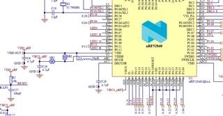
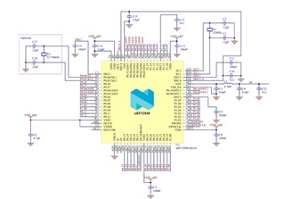
1. Which schematic/ footprint should I proceed with?

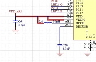
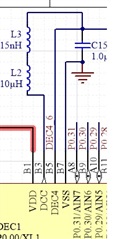
2. I am also planing to enable DCDC regulator if required. Is it ok to connect pins DCCH and VDD with a 10nH inductor, and DCC-DEC4 with series 15nH and 10uH inductors even if I don't use DCDC regulator? Please see the attachments below.


3. If I enable DCDC regulator, does it degrades RF performance? Will I have to use external RF amplification?

Thanks a lot!!

Parents Reply Children
  • Hi Andreas,

    Many thanks for the reply.

    1. I think my questions was not clear enough. Sorry about that. Actually the issue is the schematic diagram PIN positions. I am just not sure whether the layout pin positions also changes. As you can see in the first two images I have sent, VDDH, DCCH and VDD pin positions are different in two diagram. Is this just a schematic diagram or is there is a different chip variant I have to use in particularly?

    2. I checked the configuration 4. I am bit confused on the supply voltages. In this case:

       a) Actual supply voltage from the battery, should it be connected to VDD_HV or VDD_nRF?

       b) Does VDD pin acts as an output Voltage once I connect battery to VDD_HV?

  • Hi,


    1. Aha, do you mean the 'order' of the pins along the side of the schematic symbol. No this is just a difference in the schematic symbol for some reason, the ICs and the pinouts are exactly the same.
      1. Voltage from the battery is commencted to VDD_HV.
      2. Yes. You can supply external circuitry up to 25 mA if the radio is not transmitting or transmitting with 4dBm or lower, and 5 mA if the radio is transmitting at 5 dBm or higher.


    Best regards,

    Andreas

Related