Hello,
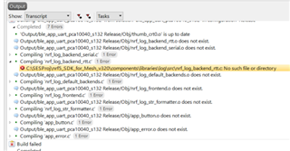
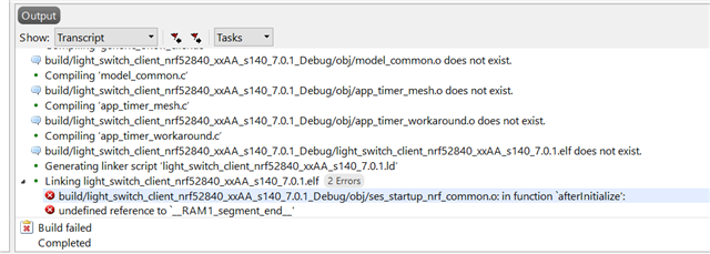
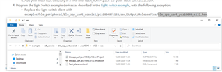
I am trying to follow the tutorial SDK UART coexistence example, but it seems like the last step cannot be completed. As you can see, that .hex file does not exist in the folder. Do you have any suggestion?
Thanks.
Hello,
I am trying to follow the tutorial SDK UART coexistence example, but it seems like the last step cannot be completed. As you can see, that .hex file does not exist in the folder. Do you have any suggestion?
Thanks.