Hello
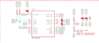
I am working on SDK v17, using nRF52832 (MDBT42Q) and MPU6050 sensor.
I tried TWI_SCANNER because I thought there was a problem getting the value of MPU6050.
However, if I proceed with the scan on this board, I will not be able to escape from 'nrf_twim_event_check' and will have an infinite loop.
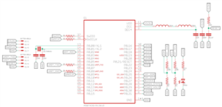
This is my main code and modified PCA10040 code.
/**
 * Copyright (c) 2016 - 2020, Nordic Semiconductor ASA
 *
 * All rights reserved.
 *
 * Redistribution and use in source and binary forms, with or without modification,
 * are permitted provided that the following conditions are met:
 *
 * 1. Redistributions of source code must retain the above copyright notice, this
 *    list of conditions and the following disclaimer.
 *
 * 2. Redistributions in binary form, except as embedded into a Nordic
 *    Semiconductor ASA integrated circuit in a product or a software update for
 *    such product, must reproduce the above copyright notice, this list of
 *    conditions and the following disclaimer in the documentation and/or other
 *    materials provided with the distribution.
 *
 * 3. Neither the name of Nordic Semiconductor ASA nor the names of its
 *    contributors may be used to endorse or promote products derived from this
 *    software without specific prior written permission.
 *
 * 4. This software, with or without modification, must only be used with a
 *    Nordic Semiconductor ASA integrated circuit.
 *
 * 5. Any software provided in binary form under this license must not be reverse
 *    engineered, decompiled, modified and/or disassembled.
 *
 * THIS SOFTWARE IS PROVIDED BY NORDIC SEMICONDUCTOR ASA "AS IS" AND ANY EXPRESS
 * OR IMPLIED WARRANTIES, INCLUDING, BUT NOT LIMITED TO, THE IMPLIED WARRANTIES
 * OF MERCHANTABILITY, NONINFRINGEMENT, AND FITNESS FOR A PARTICULAR PURPOSE ARE
 * DISCLAIMED. IN NO EVENT SHALL NORDIC SEMICONDUCTOR ASA OR CONTRIBUTORS BE
 * LIABLE FOR ANY DIRECT, INDIRECT, INCIDENTAL, SPECIAL, EXEMPLARY, OR
 * CONSEQUENTIAL DAMAGES (INCLUDING, BUT NOT LIMITED TO, PROCUREMENT OF SUBSTITUTE
 * GOODS OR SERVICES; LOSS OF USE, DATA, OR PROFITS; OR BUSINESS INTERRUPTION)
 * HOWEVER CAUSED AND ON ANY THEORY OF LIABILITY, WHETHER IN CONTRACT, STRICT
 * LIABILITY, OR TORT (INCLUDING NEGLIGENCE OR OTHERWISE) ARISING IN ANY WAY OUT
 * OF THE USE OF THIS SOFTWARE, EVEN IF ADVISED OF THE POSSIBILITY OF SUCH DAMAGE.
 *
 */
/** @file
 * @defgroup tw_scanner main.c
 * @{
 * @ingroup nrf_twi_example
 * @brief TWI Sensor Example main file.
 *
 * This file contains the source code for a sample application using TWI.
 *
 */

#include <stdio.h>
#include <stdbool.h>
#include <stdint.h>
#include "boards.h"
#include "app_util_platform.h"
#include "app_error.h"
#include "nrf_drv_twi.h"

#include "app_uart.h"
//#include "bsp.h"
#include "nrf_uart.h"
#include "nrf_uarte.h"


#include "nrf_log.h"
#include "nrf_log_ctrl.h"
#include "nrf_log_default_backends.h"

/* TWI instance ID. */
#if TWI0_ENABLED
#define TWI_INSTANCE_ID     0
#elif TWI1_ENABLED
#define TWI_INSTANCE_ID     1
#endif

 /* Number of possible TWI addresses. */
 #define TWI_ADDRESSES      127


//UART
#define MAX_TEST_DATA_BYTES     (15U)                /**< max number of test bytes to be used for tx and rx. */
#define UART_TX_BUF_SIZE 256                         /**< UART TX buffer size. */
#define UART_RX_BUF_SIZE 256                         /**< UART RX buffer size. */


/* TWI instance. */
static const nrf_drv_twi_t m_twi = NRF_DRV_TWI_INSTANCE(TWI_INSTANCE_ID);


/**
 * @brief TWI initialization.
 */
void twi_init (void)
{
    ret_code_t err_code;

    const nrf_drv_twi_config_t twi_config = {
       .scl                = ARDUINO_SCL_PIN,
       .sda                = ARDUINO_SDA_PIN,
       .frequency          = NRF_DRV_TWI_FREQ_100K,
       .interrupt_priority = APP_IRQ_PRIORITY_HIGH,
       .clear_bus_init     = false
    };

    err_code = nrf_drv_twi_init(&m_twi, &twi_config, NULL, NULL);
    APP_ERROR_CHECK(err_code);

    nrf_drv_twi_enable(&m_twi);
}


//UART
void uart_error_handle(app_uart_evt_t * p_event)
{
    if (p_event->evt_type == APP_UART_COMMUNICATION_ERROR)
    {
        APP_ERROR_HANDLER(p_event->data.error_communication);
    }
    else if (p_event->evt_type == APP_UART_FIFO_ERROR)
    {
        APP_ERROR_HANDLER(p_event->data.error_code);
    }
}

#define UART_HWFC APP_UART_FLOW_CONTROL_DISABLED

/**
 * @brief Function for main application entry.
 */
int main(void)
{
    ret_code_t err_code;
    uint8_t address;
    uint8_t sample_data;
    bool detected_device = false;

    APP_ERROR_CHECK(NRF_LOG_INIT(NULL));
    NRF_LOG_DEFAULT_BACKENDS_INIT();

    //bsp_board_init(BSP_INIT_LEDS);

    NRF_LOG_INFO("TWI scanner started.");
    NRF_LOG_FLUSH();
    twi_init();

    //UART
    /*const app_uart_comm_params_t comm_params =
      {
          RX_PIN_NUMBER,
          TX_PIN_NUMBER,
          RTS_PIN_NUMBER,
          CTS_PIN_NUMBER,
          UART_HWFC,
          false,
#if defined (UART_PRESENT)
          NRF_UART_BAUDRATE_115200
#else
          NRF_UARTE_BAUDRATE_115200
#endif
      };

    APP_UART_FIFO_INIT(&comm_params,
                         UART_RX_BUF_SIZE,
                         UART_TX_BUF_SIZE,
                         uart_error_handle,
                         APP_IRQ_PRIORITY_LOWEST,
                         err_code);

    //APP_ERROR_CHECK(err_code);*/


   // bsp_board_led_off(0);
   // bsp_board_led_off(1);
   // bsp_board_led_off(2);
    //bsp_board_led_off(3);
   // bsp_board_led_off(4);

    //printf("\r\nUART example started.\r\n");

    for (address = 1; address <= TWI_ADDRESSES; address++)
    {
        err_code = nrf_drv_twi_rx(&m_twi, address, &sample_data, sizeof(sample_data));
        if (err_code == NRF_SUCCESS)
        {
            detected_device = true;
            NRF_LOG_INFO("TWI device detected at address 0x%x.", address);
            //printf("TWI device detected at address 0x%x.", address);
            //bsp_board_led_on(1);
        }
        NRF_LOG_FLUSH();
    }

    if (!detected_device)
    {
        NRF_LOG_INFO("No device was found.");
        //printf("No device was found.");
        //bsp_board_led_on(2);
        NRF_LOG_FLUSH();
    }


    while (true)
    {
        /* Empty loop. */
    }
}

/** @} */
//Custum_pca10040.h

#ifndef PCA10040_H
#define PCA10040_H

#ifdef __cplusplus
extern "C" {
#endif

//#include "custom_feature.h"
#include "nrf_gpio.h"

#define LEDS_NUMBER    5

#define LED_START      16
#define LED_1          17
#define LED_2          19
#define LED_6          16 //LED 6~10 : BAT_LED
#define LED_7          18
#define LED_8          20
#define LED_9          30
#define LED_10         31
#define LED_STOP       31

#define LEDS_ACTIVE_STATE 0

#define LEDS_INV_MASK  LEDS_MASK

//#define LEDS_LIST { LED_1, LED_2, LED_3, LED_4 }
#define LEDS_LIST {BAT_LED_1, BAT_LED_2, BAT_LED_3, BAT_LED_4, BAT_LED_5} //LED LIST
#define LEDS_LIST2 {BAT_LED_2, BAT_LED_1, BAT_LED_4} //Left LED
#define LEDS_LIST3 {BAT_LED_2, BAT_LED_3, BAT_LED_5} //Right LED

#define BSP_LED_0      LED_1
#define BSP_LED_1      LED_2
#define BSP_LED_2      LED_3
#define BSP_LED_3      LED_4
#define BSP_LED_4      LED_5

#define BUTTONS_NUMBER 1
//#define BUTTONS_NUMBER 4

#define BUTTON_START   28
#define BUTTON_1       28
//#define BUTTON_2       14
//#define BUTTON_3       15
//#define BUTTON_4       16
#define BUTTON_STOP    28
#define BUTTON_PULL    NRF_GPIO_PIN_PULLUP

#define BUTTONS_ACTIVE_STATE 0

#define BUTTONS_LIST { BUTTON_1}

#define BSP_BUTTON_0   BUTTON_1


#define RX_PIN_NUMBER  8
#define TX_PIN_NUMBER  6
#define CTS_PIN_NUMBER 7
#define RTS_PIN_NUMBER 5
#define HWFC           true

#define SPIS_MISO_PIN   28  // SPI MISO signal.
#define SPIS_CSN_PIN    12  // SPI CSN signal.
//#define SPIS_MOSI_PIN   25  // SPI MOSI signal.
#define SPIS_SCK_PIN    29  // SPI SCK signal.

#define SPIM0_SCK_PIN   29  // SPI clock GPIO pin number.
//#define SPIM0_MOSI_PIN  25  // SPI Master Out Slave In GPIO pin number.
#define SPIM0_MISO_PIN  28  // SPI Master In Slave Out GPIO pin number.
#define SPIM0_SS_PIN    12  // SPI Slave Select GPIO pin number.

#define SPIM1_SCK_PIN   2   // SPI clock GPIO pin number.
#define SPIM1_MOSI_PIN  3   // SPI Master Out Slave In GPIO pin number.
#define SPIM1_MISO_PIN  4   // SPI Master In Slave Out GPIO pin number.
#define SPIM1_SS_PIN    5   // SPI Slave Select GPIO pin number.

#define SPIM2_SCK_PIN   12  // SPI clock GPIO pin number.
#define SPIM2_MOSI_PIN  13  // SPI Master Out Slave In GPIO pin number.
#define SPIM2_MISO_PIN  14  // SPI Master In Slave Out GPIO pin number.
#define SPIM2_SS_PIN    15  // SPI Slave Select GPIO pin number.

// serialization APPLICATION board - temp. setup for running serialized MEMU tests
/*#define SER_APP_RX_PIN              23    // UART RX pin number.
#define SER_APP_TX_PIN              24    // UART TX pin number.
#define SER_APP_CTS_PIN             2     // UART Clear To Send pin number.
//#define SER_APP_RTS_PIN             25    // UART Request To Send pin number.

#define SER_APP_SPIM0_SCK_PIN       12     // SPI clock GPIO pin number.
#define SER_APP_SPIM0_MOSI_PIN      13      // SPI Master Out Slave In GPIO pin number
#define SER_APP_SPIM0_MISO_PIN      14     // SPI Master In Slave Out GPIO pin number
#define SER_APP_SPIM0_SS_PIN        23     // SPI Slave Select GPIO pin number
//#define SER_APP_SPIM0_RDY_PIN       25     // SPI READY GPIO pin number
#define SER_APP_SPIM0_REQ_PIN       24     // SPI REQUEST GPIO pin number

// serialization CONNECTIVITY board
#define SER_CON_RX_PIN              24    // UART RX pin number.
#define SER_CON_TX_PIN              23    // UART TX pin number.
//#define SER_CON_CTS_PIN             25    // UART Clear To Send pin number. Not used if HWFC is set to false.
#define SER_CON_RTS_PIN             2     // UART Request To Send pin number. Not used if HWFC is set to false.


#define SER_CON_SPIS_SCK_PIN        27    // SPI SCK signal.
#define SER_CON_SPIS_MOSI_PIN       2     // SPI MOSI signal.
//#define SER_CON_SPIS_MISO_PIN       26    // SPI MISO signal.
#define SER_CON_SPIS_CSN_PIN        23    // SPI CSN signal.
//#define SER_CON_SPIS_RDY_PIN        25    // SPI READY GPIO pin number.
#define SER_CON_SPIS_REQ_PIN        24    // SPI REQUEST GPIO pin number. */

#define SER_CONN_CHIP_RESET_PIN     21    // Pin used to reset connectivity chip


// Arduino board mappings
#define ARDUINO_SCL_PIN             26//27    // SCL signal pin
#define ARDUINO_SDA_PIN             25//26    // SDA signal pin
#define ARDUINO_AREF_PIN            2     // Aref pin
/*#define ARDUINO_13_PIN              25    // Digital pin 13
#define ARDUINO_12_PIN              24    // Digital pin 12
#define ARDUINO_11_PIN              23    // Digital pin 11
#define ARDUINO_10_PIN              22    // Digital pin 10
#define ARDUINO_9_PIN               20    // Digital pin 9
#define ARDUINO_8_PIN               19    // Digital pin 8

#define ARDUINO_7_PIN               18    // Digital pin 7
#define ARDUINO_6_PIN               17    // Digital pin 6
#define ARDUINO_5_PIN               16    // Digital pin 5
#define ARDUINO_4_PIN               15    // Digital pin 4
#define ARDUINO_3_PIN               14    // Digital pin 3
#define ARDUINO_2_PIN               13    // Digital pin 2
#define ARDUINO_1_PIN               12    // Digital pin 1
#define ARDUINO_0_PIN               11    // Digital pin 0

#define ARDUINO_A0_PIN              2     // Analog channel 0
#define ARDUINO_A1_PIN              3     // Analog channel 1
#define ARDUINO_A2_PIN              4    // Analog channel 2
#define ARDUINO_A3_PIN              5    // Analog channel 3
#define ARDUINO_A4_PIN              28    // Analog channel 4
#define ARDUINO_A5_PIN              29    // Analog channel 5
#define ARDUINO_A6_PIN              30    // Analog channel 6
#define ARDUINO_A7_PIN              31    // Analog channel 7
*/

#define APP_BTN_1 	28 //POWER_STATE pin
//#define BAT_ADC		3 //A0
//#define BUZZER_PIN 	27

#define BAT_LED_1   16
#define BAT_LED_2   18
#define BAT_LED_3   20
#define BAT_LED_4   30
#define BAT_LED_5   31

#define Pairing_LED  19

#define POWER_OFF  29 //POWER_HOLD pin

#define bat_state	22 //battery charge state


#ifdef __cplusplus
}
#endif

#endif // PCA10040_H
Testing with the NRF52DK board will work normally. Is there a possible hardware problem?
Can I know the cause and solution of this problem?
Thank you.
=========================================================================
In nRF52DK, there is the same problem if I connect the SCL, SDA pin to 26,25 and debug it. Is this a problem with the nrf52832 pin? Should I redesign my hardware?
Thank you.