This post is older than 2 years and might not be relevant anymore
More Info: Consider searching for newer posts

Simple SPI

Hello,

I am using nrf9160 and want to test the just simple SPI function. The code that I found from github(https://github.com/Rallare/fw-nrfconnect-nrf/tree/nrf9160_samples/samples/nrf9160/spi c) is old and gives me too many errors. Are there any simple SPI code that I can try in my nrf9160 board in order to test whether I can send a simple data via SPI. I also found spi_flash_at45 however I don't have any device from at45 family to test it so another simple example would be so helpful for me. 

Thank you

Parents Reply
  • Hi Hakan,

    Thanks for the reply. This issue is kind of important for me hence I need to solve it. Did you try the code that you sent me "this simple spi loopback", with logic analyzer? Can you see the clock output and the miso properly from the logic analyzer? Seeing the spi functionality from logic analyzer is very important for me to move on in my project. Also if you are able to see it from logic analyzer can you tell me your settings in the system such as sampling freq etc.

    Thank you for the help

Children
  • Hi,


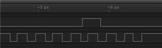
    Yes, it seems to toggle at my end:


    verulia said:
    Can you see the clock output and the miso properly from the logic analyzer?

     MISO is the "master in, slave out", so unless you have anything externally connected to the device, it will not show anything. This is why I asked if you have connected the MISO signal to the MOSI signal. This is a loopback test.


    Can you please confirm which pins aren't working, as per my former response?

    Is it only the CLK pin not outputting a signal? Please provide a screenshot of your sampled signal.

    Can you please share your current project so I can try it at my end?


    Kind regards,

    Håkon

  • Hi Hakan,

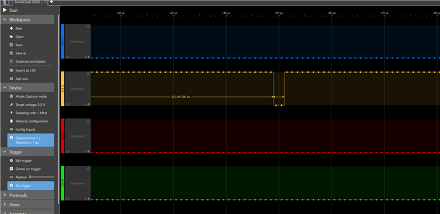
    This is the output right now. MISO AND MOSI are connected together on the nrf. clk pin is 11. I only connected clk pin<11> to logic analyzer on CH2. My sampling rate is 1 MHz rigth now. When I increase the sampling rate I only see high(1) on CH2. The code that I am using is the one in the attachment I didn't change anything in that code. Once I get this observation work I will modifiy the code and move on. I am sure that logic analyzer is working because when I toggle the pins manually I can properly observe it. I was also be able to observe the clock signal with different microcontroller(nor nrf)

    Thank you.

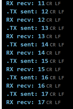
  • Also this is the output on lte link monitor when I connect MISO TO MOSI:

    so it seems there aren't any problem in loopback test functionality.

  • Hi,


    Are you able to test with 1.8V setting in your logic analyzer SW? If you're using the nRF9160-DK, its default setting is 1.8V (changeable to 3.0V via the VDD_IO switch near the power switch).


    Kind regards,

    Håkon

  • Hi Hakan,

    I already changed that it is 3V. Are you observing the clk signal without doing any triggering? Does it show up as long as you connect clk pin to logic analyzer? I didn't understand what I am doing wrong? Are my adjustmenst correct?

    -MISO AND MOSI are connected on NRF

    -Sampling freq=5Mhz(I also tried other ones no change)

    -Only clk is connected to logic analyzer

    - I am not doing any triggering currently but I tried all the triggering options nothing changed

    Thank you

Related