This post is older than 2 years and might not be relevant anymore
More Info: Consider searching for newer posts

Works OK on the DK, but not on my custom board (no radio) - NRF52832 wlcsp

Hi fellow devs:)
I'd really appreciate some advice on this please. I've come to a bit of a dead-end.
Hopefully you can spot a mistake I've made.

I am trying to produce a low cost mass producible device which basically measures temperature and broadcasts the beacon data at 1 sec intervals. Pretty simple...
Energy harvesting from a nearby induction field will charge 2 supercapacitors, which power-up the bluetooth chip.
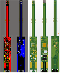
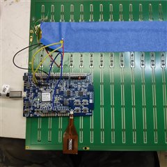
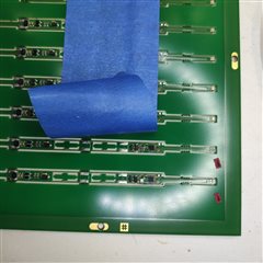
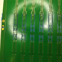
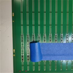
The charging side of it works ok, but for my tests I am just using a bench power supply. I have designed a custom board, long and thin, only 5mm width. That's why I chose the small 3mm WL-CSP.

My application code works just fine on the DK, radio working, advertising works.
But it does not work on my custom board. I actually made 10 boards, and all of them have the same problem.

DK: NRF52832 QFN package. Both a 32MHz and 32.768KHz crystal.
My PCB: NRF52832 WL-CSP. Only 32MHz crystal mounted.

My custom board setup:
VDD-NRF: 3.0V
SWD: Programs OK via DK NRF-Programmer.
Application: Beacon, reporting temperature data.
Problem: No radio (Advertising not found in nrf connect phone app). 

Strange symptom with my custom boards:
Advertising is briefly noticed in the nrf connect app (with scanning mode running) only during programming. After programming, nothing is seen from the radio again.
I repeated this test and monitored brief bursts of activity on the 32MHz clock
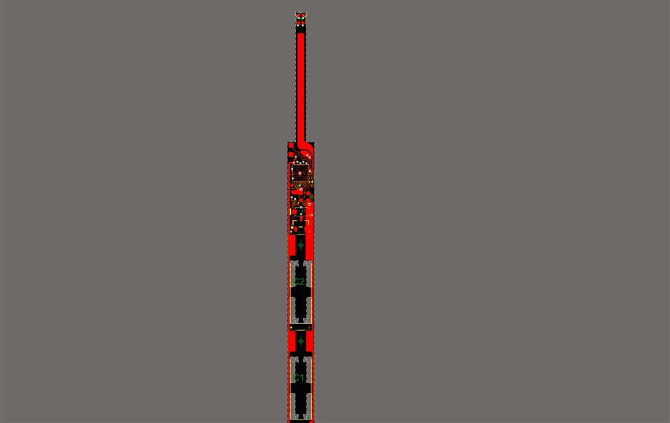
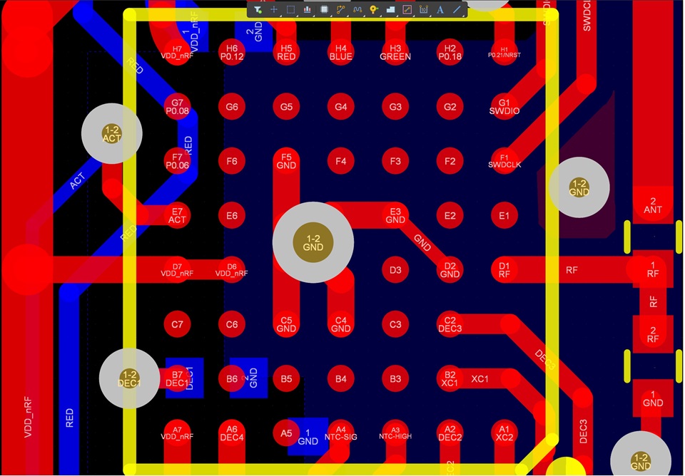
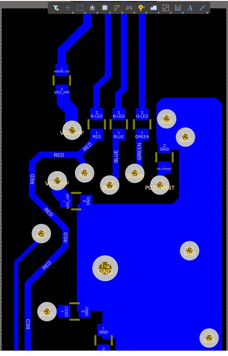
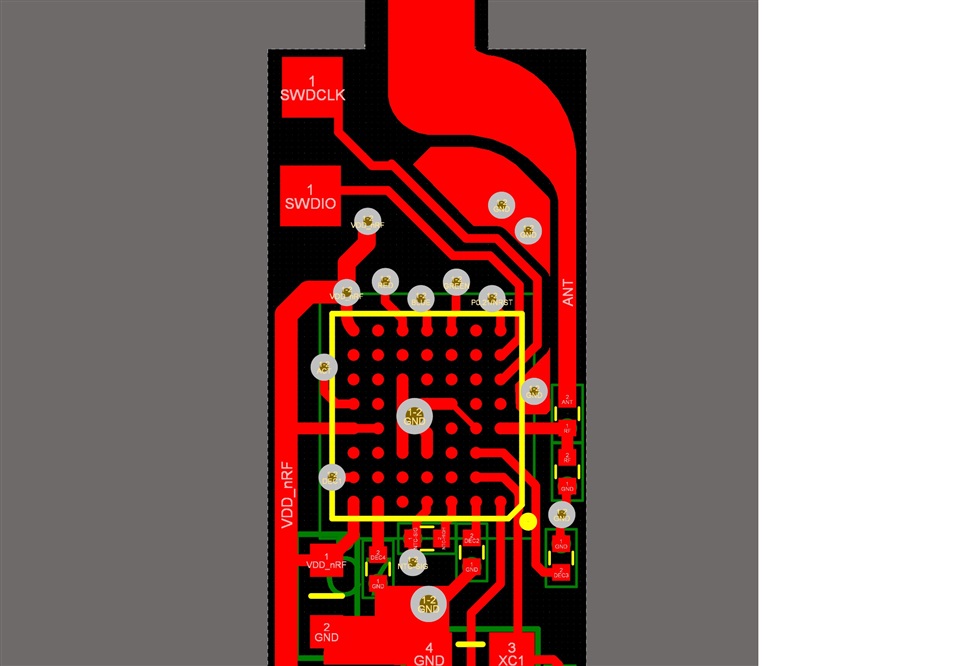
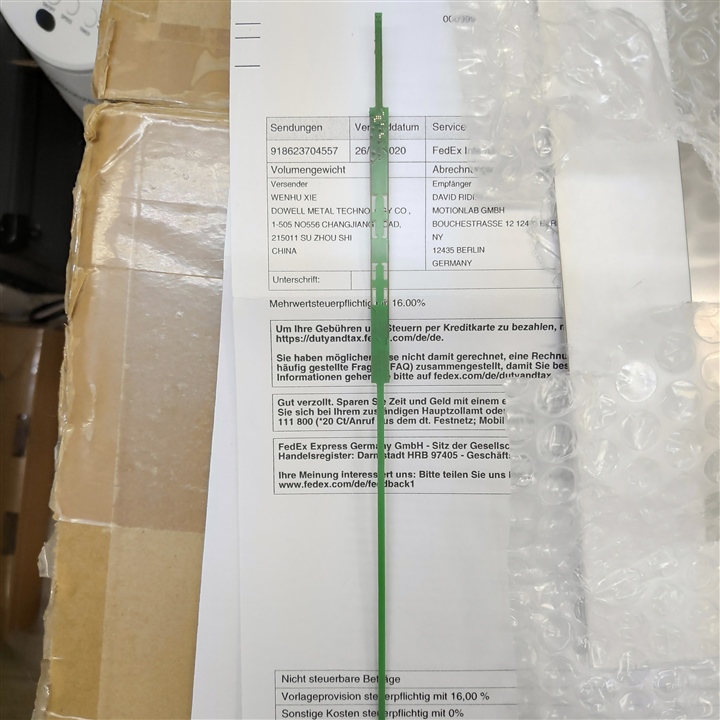
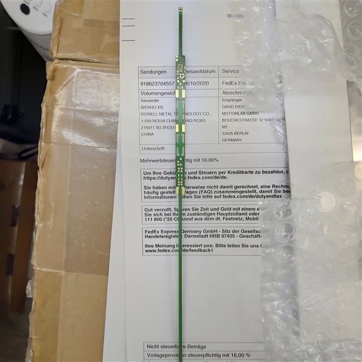


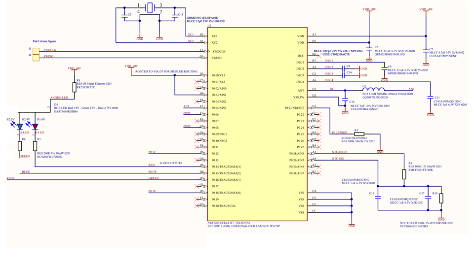
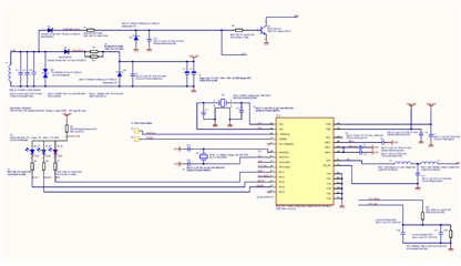
Link to the Schematic PDF


And here is my Prj.conf

CONFIG_ADC=y
CONFIG_ADC_ASYNC=y
CONFIG_ADC_LOG_LEVEL_INF=y
CONFIG_ADC_NRFX_ADC_CHANNEL_COUNT=3

CONFIG_GPIO=y

# BLUETOOTH CONFIG
CONFIG_BT=y
CONFIG_BT_DEBUG_LOG=y
CONFIG_BT_DEVICE_NAME="Heatle-Rod"

# c library
CONFIG_NEWLIB_LIBC=y

# power management
#CONFIG_SYS_POWER_MANAGEMENT=y
#CONFIG_DEVICE_POWER_MANAGEMENT=y
#CONFIG_DEVICE_IDLE_PM=y

#CONFIG_SYS_POWER_MANAGEMENT=y
#CONFIG_SYS_POWER_SLEEP_STATES=y
#CONFIG_SYS_POWER_DEEP_SLEEP_STATES=y
#CONFIG_DEVICE_POWER_MANAGEMENT=y

CONFIG_CLOCK_CONTROL_NRF_K32SRC_RC=y
#CONFIG_CLOCK_CONTROL_NRF_K32SRC_250PPM=y
#CONFIG_CLOCK_CONTROL_NRF_K32SRC_500PPM=y
#CONFIG_CLOCK_CONTROL_NRF_K32SRC_SYNTH=y
CONFIG_CLOCK_CONTROL_NRF_K32SRC_20PPM=y
CONFIG_SOC_SERIES_NRF52X=y
CONFIG_SOC_NRF52832_QFAA=y


The project C files are atatched here also.
sw-pcb-rod-ble-develop (1).zip


Kind regsrds,
David
Heatle.de

Parents
  • You need to change C3 and C13 from 12pF to 8pF. You likely have issues with the 32MHz crystal not starting up properly. 

    There are also some issues in your RF path, the impedance match and harmonics filter consisting of C12 and L2 needs to be tuned, best practice is to copy the ref layout exactly. You transmission line is likely not 50ohm. You will also have issue with the antenna, the lack of ground plane will make it hard for the antenna to resonate at the carrier frequency reducing the range, you also need a shunt capacitor to properly tune a quarter-wave monopole antenna. 

    What is the footprint at the end of the antenna for? 

  • Hey, So, I took the advice from you all, many thanks.
    Just to share the experience so far and answer some queries:

    I re-span the boards and... Basically it still doesn't work:(
    The radio still doesn't broadcast, unless we are in "Debug interface mode" we have just discovered.
    Actually I saw this kind of behavior on the old boards with intermittant short radio bursts, only during flashing.

    Software: The stock ble beacon example software from Nordic. Again, this works OK on the DK, but still not on my boards.

    List of changes (Old board as seen at the beginning of this thread):
    1. Old board: NRF52832   New: NRF52805   (both are WLSCP)
    2. Old board LF Xtal: Not-Fitted   New: 32.765KHz Fitted.
    3. Old board: 32MHz load caps: 12pF  New: 4.7pF
    4. Old board: Matching network, LC.  New: 2LC, copied 1:1 from example layout for the NRF52805.
    5. Old board: Reset Pin P0.21 pulled high.  New: N/C as recommended in the documentation.
    6. Old board: Hand assembled.  New: Pick and place by our EMS.

    New board: new improved, simpler layout. 
    Old: 2 Layers   New: Same 2 layers.
    Extra care was taken regarding light damage in manufacturing, assembly and testing, UV and IR. Dark coverings, no hot air rework station etc. Checking of the solder and paste masks was done carefully.


    The SW engineer and I can program and debug the device repetitively (no more dead chips after the first flashing which we experiened on all 6 of the 10 old boards) using the NRF connect windows program.
    The board can do LED blinky, RGB led at the very top of the board. But the radio only works when in Debug Interface Mode.
    Ie. Beacon seen on our cell phone (NRF connect App). Data received looks ok.

    Other things.
    I observed all DEC capacitance requirements and guidelines in the datasheets and example NRF52805 ref design.
    Checked the ball assignments are correct. Solder joints are good. X-ray confirmed all are OK. 
    Board is powered from the DK: 3.3V 
    DEC2 and Dec4 tied as recommended.
    Now programming using west and debugging in Visual Studio.


    My guess, from the HW perspective: Maybe somehow there is a power problem on my board, and the device is partially sinking current through the SWD interface, which causes it to work only when the interface is active, lines toggling in debug mode. Other than this theory I am at a loss. More SW tests to come...
    ROD-PCB-SCH.pdfROD-PCB-DWG.pdf


  • Hi, 

    from what I can see in the pdf of the gerber files:
    1.You must follow the reference design
    2. When designing a 2-layer pcb, you need to take have the bottom layer as mainly ground. See our guideline for nRF52805

    3. There can't be any routing under the RF path and antenna, only ground under the RF path.
    4. You need to properly ground the center pad.

    Best regards,
    Kaja

  • Hi, 

    In addition to Kaja's comments, I would like to comment on this:

    DJR said:
    But the radio only works when in Debug Interface Mode.
    Ie. Beacon seen on our cell phone (NRF connect App). Data received looks ok.

    You have not followed the reference design, this can make the design unstable, if you attached a debugger this can improve the situation marginally, just enough to make it work.

    Do you see any difference if you don't go to sleep (don't use idle_state_handle(), nrf_pwr_mgmt_run(), sd_app_evt_wait())?

    Kenneth

  • Hi Kenneth, 

    please let me shortly introduce myself. I am working with David and helping with the software side of the project.
    Thanks for the advice, I will give it a try. Just short summary of the current behavior:

    Board without debugger at power on -> Nothing happens.
    Board with debugger at power on, everything works, even when stopping the debugger.

    We connected the reset pin and the behavior is like this:

    Power on without Debugger + Reset -> Nothing happens
    Power on with      Debugger + Reset -> Restarts instantly (with and without debugger running)

    So it seems the debugger is somehow kickstarting the clocks or something.

    I will give it a try with your recommendations and report back.

    Greetings

    Ansgar

  • Hi Kenneth,

    I removed all sleep routines and still the same behavior. The blinky example is also not working. Just for clarification, your software works fine on the nRF52 DK with the board set to 52805.

    Greetings

    Ansgar

  • Hi Ansgar,

    Kenneth is out on vacation until 6th of April, but you should update the HW to get this to work.

    AnsgarSchmidt said:
    Board without debugger at power on -> Nothing happens.
    Board with debugger at power on, everything works, even when stopping the debugger.

     You might get "good enough" grounding with debugger connect and therefor it works, but you must reroute the and make sure you ground the center pad properly. Please upload updated design files for a full review, before you produce new prototypes. 

    FYI: This case i public, make if private if you feel this is sensitive information to share in this case, or make a new case for HW review. 

    Best regards,
    Kaja

Reply
  • Hi Ansgar,

    Kenneth is out on vacation until 6th of April, but you should update the HW to get this to work.

    AnsgarSchmidt said:
    Board without debugger at power on -> Nothing happens.
    Board with debugger at power on, everything works, even when stopping the debugger.

     You might get "good enough" grounding with debugger connect and therefor it works, but you must reroute the and make sure you ground the center pad properly. Please upload updated design files for a full review, before you produce new prototypes. 

    FYI: This case i public, make if private if you feel this is sensitive information to share in this case, or make a new case for HW review. 

    Best regards,
    Kaja

Children
No Data
Related