Beware that this post is related to an SDK in maintenance mode
More Info: Consider nRF Connect SDK for new designs
This post is older than 2 years and might not be relevant anymore
More Info: Consider searching for newer posts

nRF52832 SAADC inaccurate measurement

Hi!

I'm working on using the SAADC in 14-bit sampling mode (oversampling set to x2) using nRF SDK 17. The supply voltage for my chip is 3.3V, and I have the reference set to VDD4 with a gain of 4. My understanding is that I should be able to get a resolution of roughly 0.2mV per bit with some fudge factor of noise.My sampling rate is roughly once per second with an acquisition time of 3us.

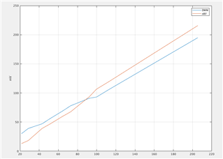
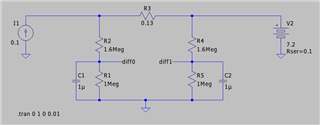
Please reference the rough schematic below for details. I'm experimenting with using the SAADC to measure the shunt voltage from a battery management system to a given attached battery. In the example I chose a current of 100mA, which should result in a shunt voltage of 13mV and a measured differential (between diff0 and diff1) of 5mV. Unfortunately this example, and even the case where I'm pumping 1A through the circuit do not give me the values I expect when compared to a DMM. Is there something weird going on with the extra apparent resistance due to the voltage divider? Maybe the SAADC isn't as accurate as I thought? I'm at a bit of a loss at the moment. Below is also some of the configuration code:

nrf_saadc_channel_config_t conf = {.resistor_n = NRF_SAADC_RESISTOR_DISABLED,
	                                   .resistor_p = NRF_SAADC_RESISTOR_DISABLED,
	                                   .gain = NRF_SAADC_GAIN1_4,
	                                   .reference = NRF_SAADC_REFERENCE_VDD4,
	                                   .acq_time = NRF_SAADC_ACQTIME_3US,
	                                   .mode = NRF_SAADC_MODE_DIFFERENTIAL,
	                                   .burst = NRF_SAADC_BURST_DISABLED,
	                                   .pin_p = convert_to_saadc_address(coil_pin),
	                                   .pin_n = convert_to_saadc_address(diff_pin)};
	                                   
nrf_drv_saadc_config_t saadc_config = NRF_DRV_SAADC_DEFAULT_CONFIG;
saadc_config.resolution = NRF_SAADC_RESOLUTION_14BIT;

Thanks!

Parents
  • Hello,

    Please reference the rough schematic below for details.

    Thank you for including a rough schematic - this is very helpful in order to quickly familiarize with the issue.
    My immediate thought when seeing this schematic is that your capacitors C1 and C2 are enormous for the task.
    I have not done any calculations on this yet, but I suspect that it takes a very long time to get the correct voltage levels here with such big capacitors. 
    If you have not seen it already, I highly recommend reading through this blog post detailing how to measure the voltage of a lithium ion battery. In the blogpost, the circuit design and calculations are demonstrated.

    Could you go through the blogpost I referenced above, and recheck your capacitor value-calculations, and then try again with the new capacitor values if the results diverge from your previous calculations?
    You could also share your previous capacitor value calculation, and I'll take a look.

    For future debugging it would also be helpful if you could include some of the SAADC outputs you are seeing, compared to the value you are measuring with your DMM.

    On a general note I would also recommend using the internal 600 mV reference when measuring VDD voltage, since the results using VDD4 when measuring VDD will skew over time(as the battery discharges).

    Best regards,
    Karl

  • Thanks for the fast reply!

    Thank you for including a rough schematic

    No problem, I try to give as much info as I can.

    I did see that tutorial, it was very helpful in understanding the SAADC a little better and was actually the reason I added capacitors in the first place. I oversized the caps in an attempt to make the final BOM a touch cheaper, and figured the increase in size wouldn't hurt. I didn't really do any calculations beyond the tutorial you referenced figuring that was a lower bound on what was required.

    I just wen't through some probably over-simplified math, my understanding is that the Thevinin resistance would be 620k, and approximating a fully charged capacitor to be at 5 time constants would give me 5*R*C=3.1 seconds. I'll go through the calculations you pointed out again and see what I get, do you think having a smaller capacitor would help? The battery is always plugged in, so I shouldn't have to worry about the charge up time in theory.

    For future debugging it would also be helpful if you could include some of the SAADC outputs you are seeing, compared to the value you are measuring with your DMM.

    Sure! As an example reading, from my Fluke 87 I'm seeing 195mV, and the microcontroller is reporting 216mV after applying the following math: (raw_value * 3.3)/(2^14) * 2.6. Where the extra 2.6 is from the voltage divider. The actual code is as follows (fixed point, three decimal places, trying to avoid floating point ops for performance):

    26 * (raw_data * 330) / (1 << 14);

    Here are several sample readings:

    DMM Characteristic Value
    195 215.8
    106 119.6
    93 106.6
    91 93.6
    78 67.6
    69 59.8
    56 46.8
    47 39
    39 18.2
    30 13

    Here's a plot of the values, the x-axis is averaged between the DMM and nRF readings to make the plot appear more linear:

    On a general note I would also recommend using the internal 600 mV reference when measuring VDD voltage, since the results using VDD4 when measuring VDD will skew over time(as the battery discharges).

    Makes sense, do you know how this would/could affect the range and/or accuracy? Though I think in my setup it doesn't matter as much since the battery voltage goes through a buck converter before being consumed by the nRF chip.

Reply
  • Thanks for the fast reply!

    Thank you for including a rough schematic

    No problem, I try to give as much info as I can.

    I did see that tutorial, it was very helpful in understanding the SAADC a little better and was actually the reason I added capacitors in the first place. I oversized the caps in an attempt to make the final BOM a touch cheaper, and figured the increase in size wouldn't hurt. I didn't really do any calculations beyond the tutorial you referenced figuring that was a lower bound on what was required.

    I just wen't through some probably over-simplified math, my understanding is that the Thevinin resistance would be 620k, and approximating a fully charged capacitor to be at 5 time constants would give me 5*R*C=3.1 seconds. I'll go through the calculations you pointed out again and see what I get, do you think having a smaller capacitor would help? The battery is always plugged in, so I shouldn't have to worry about the charge up time in theory.

    For future debugging it would also be helpful if you could include some of the SAADC outputs you are seeing, compared to the value you are measuring with your DMM.

    Sure! As an example reading, from my Fluke 87 I'm seeing 195mV, and the microcontroller is reporting 216mV after applying the following math: (raw_value * 3.3)/(2^14) * 2.6. Where the extra 2.6 is from the voltage divider. The actual code is as follows (fixed point, three decimal places, trying to avoid floating point ops for performance):

    26 * (raw_data * 330) / (1 << 14);

    Here are several sample readings:

    DMM Characteristic Value
    195 215.8
    106 119.6
    93 106.6
    91 93.6
    78 67.6
    69 59.8
    56 46.8
    47 39
    39 18.2
    30 13

    Here's a plot of the values, the x-axis is averaged between the DMM and nRF readings to make the plot appear more linear:

    On a general note I would also recommend using the internal 600 mV reference when measuring VDD voltage, since the results using VDD4 when measuring VDD will skew over time(as the battery discharges).

    Makes sense, do you know how this would/could affect the range and/or accuracy? Though I think in my setup it doesn't matter as much since the battery voltage goes through a buck converter before being consumed by the nRF chip.

Children
  • macklenc said:
    Thanks for the fast reply!

    No problem at all, I am happy to help!

    macklenc said:
    I oversized the caps in an attempt to make the final BOM a touch cheaper, and figured the increase in size wouldn't hurt. I didn't really do any calculations beyond the tutorial you referenced figuring that was a lower bound on what was required.

    Ah, I see. I must recommend that you always do these calculations prior to building a circuit, so that you have full control over what to expect when the circuit is live.
    As you can see from the tutorial, the calculated capacitor value they arrive at is 10 nF - which is 100 times smaller than the 1 µF you currently are using.

    macklenc said:
    and approximating a fully charged capacitor to be at 5 time constants would give me 5*R*C=3.1 seconds.

    How often do you intend to sample - are you not sampling every second?

    macklenc said:
    I'll go through the calculations you pointed out again and see what I get, do you think having a smaller capacitor would help?

    Yes, a smaller capacitor will charge faster - it needs to be small enough to have reached the steady-state voltage level in time for your sampling, for your measurements to be accurate.

    macklenc said:
    Sure! As an example reading, from my Fluke 87 I'm seeing 195mV, and the microcontroller is reporting 216mV after applying the following math: (raw_value * 3.3)/(2^14) * 2.6. Where the extra 2.6 is from the voltage divider. The actual code is as follows (fixed point, three decimal places, trying to avoid floating point ops for performance):

    Thank you for clarifying!
    Could you also share with me the SAADC and channel configuration you are using?
    You will need to expect some LSB of noise in your measurements, so what you describe here could in part be a result of your chosen input range.

    macklenc said:
    Makes sense, do you know how this would/could affect the range and/or accuracy? Though I think in my setup it doesn't matter as much since the battery voltage goes through a buck converter before being consumed by the nRF chip.

    If you externally ensure that the supplied VDD is constant, then I suppose this will not be an issue for you.
    However, in the case that VDD is declining with the voltage level of the battery, then your measurements over time will get skewed since the measurements rely on a non-constant reference.
    The degree of skewing will depend on the VDD range of your supply.

    Best regards,
    Karl

  • Hey Karl, sorry about the slow reply, I've been trying to get as much data collected as possible.

    How often do you intend to sample - are you not sampling every second?

    I am sampling about once a second, but the nRF shouldn't be able to drain an entire 1uF after it's charged, right? But I will give installing new capacitors a try, unfortunately it's not easy to modify the current platform so it'll be one of the last things I try just in case I have to go back.

    Could you also share with me the SAADC and channel configuration you are using?

    I think I added the relevant configs to the original post, did I miss anything there? We are doing some fancy stuff by sampling 6 of the ADC channels in single-ended mode, but two of the pins are reserved for differential measurement.

    If you externally ensure that the supplied VDD is constant, then I suppose this will not be an issue for you.

    I think you may be on to something there, I double checked the Vpp noise on the 3.3V rail, and it does oscillate by about 10mVpp due to the buck converter. I've tasked our resident engineer with testing the accuracy when measuring with the 0.6V reference.

    As a side note, I did try to measure the differential voltage with an oscilloscope at the ADC pins, but the impedance was so high all I was able to read was an AC 60Hz signal, probably coming from mains in the building. Though that AC signal vanishes when I read one pin relative to ground, so I'm not 100% sure that the signal I'm seeing doesn't exist on the board.

    I'll report back with the findings from the new ADC reference as soon as I can. Thanks again!

  • macklenc said:
    sorry about the slow reply

    No problem at all - we'll proceed whenever you are ready, no worries.

    macklenc said:
    I am sampling about once a second, but the nRF shouldn't be able to drain an entire 1uF after it's charged, right?

    This is correct - the capacitor will not be completely drained by the sampling - so as long as the capacitor has enough time in between samples to always reach its steady state charge, then it would be fine. 
    However, the capacitor does not need to be drained entirely for the samplings to be off - in your case, the capacitor takes much longer than the sampling interval to fill completely, and because of the unlinearity of capacitor charging curves, it will never make it to the steady state once sampling starts, and thus your samples will always be fluctuating because of it.
    So, by oversizing the capacitor you are also increasing the time required in between samples to ensure correct readings.

    macklenc said:
    But I will give installing new capacitors a try, unfortunately it's not easy to modify the current platform so it'll be one of the last things I try just in case I have to go back.

    Perhaps you could test just the sampling part of a separate platform, instead of modifying your main test platform, to see how this improves your sampling accuracy.
    Alternatively, you could also test the effects of this on your current platform by increasing the time between samples to match or exceed the required charging time of your capacitors.

    macklenc said:
    I think I added the relevant configs to the original post, did I miss anything there? We are doing some fancy stuff by sampling 6 of the ADC channels in single-ended mode, but two of the pins are reserved for differential measurement.

    The config you showed there covers the main parameters, but it would be good to see the entire section where you setup and configure the SAADC.
    I suppose this can wait until the capacitor-size tests have concluded, if you are reluctant to share code.

    macklenc said:
    I'll report back with the findings from the new ADC reference as soon as I can. Thanks again!

    Great, I look forward to hearing how the tests went! :) 

    Best regards,
    Karl 

Related