This post is older than 2 years and might not be relevant anymore
More Info: Consider searching for newer posts

Having both U.FL and Trace Antenna with Zero Ohm resistor?

We are thinking to evaluate both the U.FL and Trace Antenna options on a custom nRF52840 prototype board.

1. Referring to this discussion, point 3 is about provisioning two antenna types. I understand that by using zero ohm resistor i.e., by populating/de-populating the antenna type could be selected/unselected respectively.

2. However, in other discussion, leaving the resistor pads unconnected would impact the signal because the pads would act as transmission line.

Suggestion needed:

It's a 4 layer board, having calculated the trace-width for 50-ohm impedance matching trace using the parameters of the PCB fabricator. I have replicated the nRF52840-DK trace antenna and SWF connector connections.

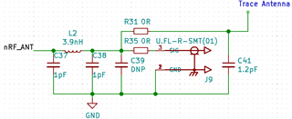
1. I can think of this simple circuit with 0-ohm (R31 & R35) in series on both the antenna lines: (I need a suggestion for PCB layout for this circuit). With this approach, I guess the 0-ohm resistor would have a negative impact on RF signal because it would impact the 50-ohm impedance matching trace.
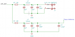
2. The other option, is to have two LC networks as seen above with 0-ohm connected to nRF_ANT pin.
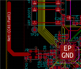
This is Work In Progress, replicating nRF52840 DK antenna and SWF connector traces:
Parents Reply Children
  • Hi,

    I am sorry for not getting back to you. Which PCB antenna design you choose is totally up to you, both designs are good alternatives depending on what you are looking for. You can use any known PCB antenna designed for 2.4GHz and achieve good range and performance.

    It's important that you follow the antenna design closely though, and it's also recommended to use the same thickness and type of PCB material used in any reference design of the antenna design your are using.

    You will anyways need to tune the choosen antenna to your own board. I recommend you add some extra length so the antenna can be made slightly shorter when tuning.

    As a general rule, a longer (full sized) antenna will give you better performance than a cut down or shrinked antenna, so if you have space in your design I would recommended to use a 1/4 wave monopole antenna (as the one used in the nRF52840 DK). You can find a whitepaper about how to design your own quarter wave antenna here.

    You should also consider the size of the ground plane in your board. A small ground plane will lead to less antenna gain, no matter what antenna you use. A meander antenna (as the one used in the TI dongle) takes less space so it's a popular choice for USB dongles and other small PCBs, but a dongle will benefit from the added ground plane in a the PC so you can have OK performance with a small antenna. Using this antenna in a small PCB will give you less range than using a 1/4 wave antenna.

    I don't know if you shared the size of the PCB you are making, but based on all this I will go for the f-inverted meander if you have a small PCB or module which will be connected to a larger ground plane, or if your PCB is larger and you have the space go for a 1/4 wave monopole antenna.

    Best regards,

    Marjeris

  • Thanks for answering , I would now mark this thread as answered.

Related