This post is older than 2 years and might not be relevant anymore
More Info: Consider searching for newer posts

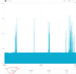
PWM consume high power near 300uA

Hi,

I am using SDK15.3.0 and s132_nrf52_6.1.1_softdevice.  (nRF52832)

Getting higher current consumption (300uA) while using the PWM library. (https://infocenter.nordicsemi.com/topic/com.nordic.infocenter.sdk5.v15.3.0/pwm_example.html)

Also tried to generate using PPI, But the same result as PWM library.

I wonder when used a low-power PWM library and got 460uA. (https://infocenter.nordicsemi.com/topic/com.nordic.infocenter.sdk5.v15.3.0/low_power_pwm_example.html

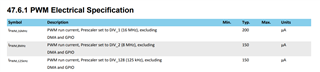
200uA somewhat expected as per the datasheet, But is there any other way to generate PWM using low power? (<200uA)

Thanks,

Nirav Patel

  • Hi,


    200uA somewhat expected as per the datasheet

     This is for the PWM peripheral, but as mentioned in the PS, it does not include GPIO, DMA current. I don't think clock current is part of this either. But PWM library and low_power_pwm_example does not use the PWM peripheral.

    What PWM frequency and duty cycle do you need ?

  • Thanks, Sigurd

    1kHz frequency and duty cycle 0 to 100%.

    PWM library uses timers so I doubt that it consumes power. (120uA max while using a timer at 16Mhz)

    Also used timers while generated PWM using PPI(custom logic). (300uA)

    Got the link to the case in which RTC used for PWM. But getting 120uA while using this.

    https://devzone.nordicsemi.com/f/nordic-q-a/58091/glitches-when-toggling-pin-with-rtc-ppi-gpiote-and-reading-rtc-s-counter

    Is there any other way except above to generate PWM but consumption shouldn't increase more than 20-30uA.

  • Sigurd,

    I got another code from the below link by using this ability to generate PWM using RTC with <30uA (Frequency 1kHz)

    https://devzone.nordicsemi.com/f/nordic-q-a/32673/current-consumption-rtc--ppi---gpiote-on-nrf52

    Did minor modification to generate PWM with different duty cycle (1 to 99%). Used COMPARE_1 to handle it.

    In between, I observed that sometimes getting inverted PWM output when changing CC value of COMPARE_1 to change duty cycle.

    Ex. Duty cycle change to 20%, with 20% duty cycle it must be HIGH for 20% and LOW for rest 80% but when the issue occurred it will be HIGH for 80% and LOW for 20%.

    May be issue occurred because the pin configured to do the TOGGLE operation.

    void gpiote_config(void)
    {
        ret_code_t err_code = NRF_SUCCESS;
        
        err_code = nrf_drv_gpiote_init();
        APP_ERROR_CHECK(err_code);
        
        nrf_drv_gpiote_out_config_t config = GPIOTE_CONFIG_OUT_TASK_TOGGLE(true);
        
        err_code = nrf_drv_gpiote_out_init(GPIO_OUTPUT_PIN_NUMBER, &config);
        APP_ERROR_CHECK(err_code);
        
        nrf_drv_gpiote_out_task_enable(GPIO_OUTPUT_PIN_NUMBER);
        
    }
    
    /** @brief Function for initializing the PPI peripheral.
    */
    void ppi_init(void)
    {
        uint32_t err_code = NRF_SUCCESS;
    
        err_code = nrf_drv_ppi_init();
        APP_ERROR_CHECK(err_code);
    
        err_code = nrf_drv_ppi_channel_alloc(&ppi_channel);
        APP_ERROR_CHECK(err_code);
        err_code = nrf_drv_ppi_channel_assign(ppi_channel,
                                              nrf_rtc_event_address_get(rtc.p_reg, NRF_RTC_EVENT_COMPARE_0),
                                              nrf_drv_gpiote_out_task_addr_get(GPIO_OUTPUT_PIN_NUMBER));
        APP_ERROR_CHECK(err_code);
        
        err_code = nrf_drv_ppi_channel_fork_assign(ppi_channel, nrf_rtc_task_address_get(rtc.p_reg, NRF_RTC_TASK_CLEAR));
        APP_ERROR_CHECK(err_code);
    	
    	/* Modification */
    	err_code = nrf_drv_ppi_channel_alloc(&ppi_channel2);
        APP_ERROR_CHECK(err_code);
        err_code = nrf_drv_ppi_channel_assign(ppi_channel2,
                                              nrf_rtc_event_address_get(rtc.p_reg, NRF_RTC_EVENT_COMPARE_1),
                                              nrf_drv_gpiote_out_task_addr_get(_pwmPin));
        APP_ERROR_CHECK(err_code);
    	/* END */
    
        // Enable both configured PPI channels
        err_code = nrf_drv_ppi_channel_enable(ppi_channel);
        APP_ERROR_CHECK(err_code);
    	/* Modification */
    	err_code = nrf_drv_ppi_channel_enable(ppi_channel2);
        APP_ERROR_CHECK(err_code);
    	/* END */
    }

    Can we configure the pin to set high while CC_0 event and low when CC_1 compared?

    Like, configure the same pin in "NRFX_GPIOTE_CONFIG_OUT_TASK_LOW" and NRFX_GPIOTE_CONFIG_OUT_TASK_HIGH".

    In this way, I can fix the issue of an inverted waveform.

    void gpiote_config(void)
    {
        ret_code_t err_code = NRF_SUCCESS;
        
        err_code = nrf_drv_gpiote_init();
        APP_ERROR_CHECK(err_code);
        
        nrf_drv_gpiote_out_config_t config = GPIOTE_CONFIG_OUT_TASK_HIGH;
    	nrf_drv_gpiote_out_config_t config1 = GPIOTE_CONFIG_OUT_TASK_LOW;
        
        err_code = nrf_drv_gpiote_out_init(GPIO_OUTPUT_PIN_NUMBER, &config);
        APP_ERROR_CHECK(err_code);
    	err_code = nrf_drv_gpiote_out_init(GPIO_OUTPUT_PIN_NUMBER, &config1);
        APP_ERROR_CHECK(err_code);
        
        nrf_drv_gpiote_out_task_enable(GPIO_OUTPUT_PIN_NUMBER);
        
    }

    Is it possible?

    Thanks,

    Nirav Patel

  • Is it possible?

    Yes. Try something like this:

    /**
     * Copyright (c) 2014 - 2021, Nordic Semiconductor ASA
     * 
     * All rights reserved.
     * 
     * Redistribution and use in source and binary forms, with or without modification,
     * are permitted provided that the following conditions are met:
     * 
     * 1. Redistributions of source code must retain the above copyright notice, this
     *    list of conditions and the following disclaimer.
     * 
     * 2. Redistributions in binary form, except as embedded into a Nordic
     *    Semiconductor ASA integrated circuit in a product or a software update for
     *    such product, must reproduce the above copyright notice, this list of
     *    conditions and the following disclaimer in the documentation and/or other
     *    materials provided with the distribution.
     * 
     * 3. Neither the name of Nordic Semiconductor ASA nor the names of its
     *    contributors may be used to endorse or promote products derived from this
     *    software without specific prior written permission.
     * 
     * 4. This software, with or without modification, must only be used with a
     *    Nordic Semiconductor ASA integrated circuit.
     * 
     * 5. Any software provided in binary form under this license must not be reverse
     *    engineered, decompiled, modified and/or disassembled.
     * 
     * THIS SOFTWARE IS PROVIDED BY NORDIC SEMICONDUCTOR ASA "AS IS" AND ANY EXPRESS
     * OR IMPLIED WARRANTIES, INCLUDING, BUT NOT LIMITED TO, THE IMPLIED WARRANTIES
     * OF MERCHANTABILITY, NONINFRINGEMENT, AND FITNESS FOR A PARTICULAR PURPOSE ARE
     * DISCLAIMED. IN NO EVENT SHALL NORDIC SEMICONDUCTOR ASA OR CONTRIBUTORS BE
     * LIABLE FOR ANY DIRECT, INDIRECT, INCIDENTAL, SPECIAL, EXEMPLARY, OR
     * CONSEQUENTIAL DAMAGES (INCLUDING, BUT NOT LIMITED TO, PROCUREMENT OF SUBSTITUTE
     * GOODS OR SERVICES; LOSS OF USE, DATA, OR PROFITS; OR BUSINESS INTERRUPTION)
     * HOWEVER CAUSED AND ON ANY THEORY OF LIABILITY, WHETHER IN CONTRACT, STRICT
     * LIABILITY, OR TORT (INCLUDING NEGLIGENCE OR OTHERWISE) ARISING IN ANY WAY OUT
     * OF THE USE OF THIS SOFTWARE, EVEN IF ADVISED OF THE POSSIBILITY OF SUCH DAMAGE.
     * 
     */
    /** @file
     * @defgroup rtc_example_main main.c
     * @{
     * @ingroup rtc_example
     * @brief Real Time Counter Example Application main file.
     *
     * This file contains the source code for a sample application using the Real Time Counter (RTC).
     *
     */
    
    #include "nrf.h"
    #include "nrf_gpio.h"
    #include "nrf_drv_rtc.h"
    #include "nrf_drv_clock.h"
    #include "boards.h"
    #include "app_error.h"
    #include <stdint.h>
    #include <stdbool.h>
    #include "nrf_drv_gpiote.h"
    #include "nrf_drv_ppi.h"
    
    
    #define USE_PPI 1
    
    #define GPIO_OUTPUT_PIN_NUMBER 3
    
    // Set RTC2_ENABLED to 1 in sdk_config.h
    static nrf_drv_rtc_t rtc = NRF_DRV_RTC_INSTANCE(2); /**< Declaring an instance of nrf_drv_rtc for RTC2. */
    static nrf_ppi_channel_t ppi_channel;s
    static nrf_ppi_channel_t ppi_channel2;
    
    void rtc_event_handler(nrf_drv_rtc_int_type_t int_type)
    {
        nrf_drv_rtc_disable(&rtc);
        nrf_drv_rtc_counter_clear(&rtc);
        nrf_drv_rtc_int_enable(&rtc, NRF_RTC_INT_COMPARE0_MASK);
        nrf_drv_rtc_enable(&rtc);
        
        nrf_gpio_pin_toggle(GPIO_OUTPUT_PIN_NUMBER);
    }
    
    
    /** @brief Function starting the internal LFCLK XTAL oscillator.
     */
    static void lfclk_config(void)
    {
        ret_code_t err_code = nrf_drv_clock_init();
        APP_ERROR_CHECK(err_code);
    
        nrf_drv_clock_lfclk_request(NULL);
    }
    
    void gpio_config(void)
    {
        nrf_gpio_cfg_output(GPIO_OUTPUT_PIN_NUMBER);
    }
    
    void gpiote_config(void)
    {
        ret_code_t err_code = NRF_SUCCESS;
        
        err_code = nrf_drv_gpiote_init();
        APP_ERROR_CHECK(err_code);
        
        nrf_drv_gpiote_out_config_t config = GPIOTE_CONFIG_OUT_TASK_TOGGLE(true);
        
        err_code = nrf_drv_gpiote_out_init(GPIO_OUTPUT_PIN_NUMBER, &config);
        APP_ERROR_CHECK(err_code);
        
        nrf_drv_gpiote_out_task_enable(GPIO_OUTPUT_PIN_NUMBER);
        
    }
    
    /** @brief Function for initializing the PPI peripheral.
    */
    void ppi_init(void)
    {
        uint32_t err_code = NRF_SUCCESS;
    
        err_code = nrf_drv_ppi_init();
        APP_ERROR_CHECK(err_code);
    
        err_code = nrf_drv_ppi_channel_alloc(&ppi_channel);
        APP_ERROR_CHECK(err_code);
        err_code = nrf_drv_ppi_channel_assign(ppi_channel,
                                              nrf_rtc_event_address_get(rtc.p_reg, NRF_RTC_EVENT_COMPARE_0),
                                              nrf_drv_gpiote_out_task_addr_get(GPIO_OUTPUT_PIN_NUMBER));
        APP_ERROR_CHECK(err_code);
    
    
        	/* Modification */
    	err_code = nrf_drv_ppi_channel_alloc(&ppi_channel2);
        APP_ERROR_CHECK(err_code);
        err_code = nrf_drv_ppi_channel_assign(ppi_channel2,
                                              nrf_rtc_event_address_get(rtc.p_reg, NRF_RTC_EVENT_COMPARE_1),
                                              nrf_drv_gpiote_out_task_addr_get(GPIO_OUTPUT_PIN_NUMBER));
        APP_ERROR_CHECK(err_code);
    	/* END */
    
                err_code = nrf_drv_ppi_channel_fork_assign(ppi_channel2, nrf_rtc_task_address_get(rtc.p_reg, NRF_RTC_TASK_CLEAR));
        APP_ERROR_CHECK(err_code);
    
    
        // Enable both configured PPI channels
        err_code = nrf_drv_ppi_channel_enable(ppi_channel);
        APP_ERROR_CHECK(err_code);
    
        	/* Modification */
    	err_code = nrf_drv_ppi_channel_enable(ppi_channel2);
        APP_ERROR_CHECK(err_code);
    	/* END */
    }
    
    /** @brief Function initialization and configuration of RTC driver instance.
     */
    static void rtc_config(void)
    {
        uint32_t err_code;
    
        uint32_t compare_val = RTC_US_TO_TICKS(20000UL, RTC_DEFAULT_CONFIG_FREQUENCY);
    
        uint32_t compare_val2 = RTC_US_TO_TICKS(100000UL, RTC_DEFAULT_CONFIG_FREQUENCY);
    
        //Initialize RTC instance
        nrf_drv_rtc_config_t config = NRF_DRV_RTC_DEFAULT_CONFIG;
        
    #ifdef USE_PPI 
        err_code = nrf_drv_rtc_init(&rtc, &config, NULL);
        APP_ERROR_CHECK(err_code);
        //Set compare channel to trigger interrupt after COMPARE_COUNTERTIME seconds
        err_code = nrf_drv_rtc_cc_set(&rtc,0, compare_val, false);
        APP_ERROR_CHECK(err_code);
        err_code = nrf_drv_rtc_cc_set(&rtc,1, compare_val2, false);
        APP_ERROR_CHECK(err_code);
    #else
        err_code = nrf_drv_rtc_init(&rtc, &config, rtc_event_handler);
        APP_ERROR_CHECK(err_code);
        //Set compare channel to trigger interrupt after COMPARE_COUNTERTIME seconds
        err_code = nrf_drv_rtc_cc_set(&rtc,0, compare_val, true);
        APP_ERROR_CHECK(err_code);
    #endif
    }
    
    /**
     * @brief Function for application main entry.
     */
    int main(void)
    {
        lfclk_config();
        rtc_config();
    #ifdef USE_PPI
        gpiote_config();    
        ppi_init();
    #else
        gpio_config();
    #endif 
        //Power on RTC instance
        nrf_drv_rtc_enable(&rtc);
        while (true)
        {
            __SEV();
            __WFE();
            __WFE();
        }
    }
    
    
    /**  @} */
    

Related