This post is older than 2 years and might not be relevant anymore
More Info: Consider searching for newer posts

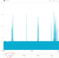
PWM consume high power near 300uA

Hi,

I am using SDK15.3.0 and s132_nrf52_6.1.1_softdevice.  (nRF52832)

Getting higher current consumption (300uA) while using the PWM library. (https://infocenter.nordicsemi.com/topic/com.nordic.infocenter.sdk5.v15.3.0/pwm_example.html)

Also tried to generate using PPI, But the same result as PWM library.

I wonder when used a low-power PWM library and got 460uA. (https://infocenter.nordicsemi.com/topic/com.nordic.infocenter.sdk5.v15.3.0/low_power_pwm_example.html

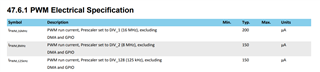
200uA somewhat expected as per the datasheet, But is there any other way to generate PWM using low power? (<200uA)

Thanks,

Nirav Patel

Parents
  • Hi,


    200uA somewhat expected as per the datasheet

     This is for the PWM peripheral, but as mentioned in the PS, it does not include GPIO, DMA current. I don't think clock current is part of this either. But PWM library and low_power_pwm_example does not use the PWM peripheral.

    What PWM frequency and duty cycle do you need ?

  • Sigurd,

    I got another code from the below link by using this ability to generate PWM using RTC with <30uA (Frequency 1kHz)

    https://devzone.nordicsemi.com/f/nordic-q-a/32673/current-consumption-rtc--ppi---gpiote-on-nrf52

    Did minor modification to generate PWM with different duty cycle (1 to 99%). Used COMPARE_1 to handle it.

    In between, I observed that sometimes getting inverted PWM output when changing CC value of COMPARE_1 to change duty cycle.

    Ex. Duty cycle change to 20%, with 20% duty cycle it must be HIGH for 20% and LOW for rest 80% but when the issue occurred it will be HIGH for 80% and LOW for 20%.

    May be issue occurred because the pin configured to do the TOGGLE operation.

    void gpiote_config(void)
    {
        ret_code_t err_code = NRF_SUCCESS;
        
        err_code = nrf_drv_gpiote_init();
        APP_ERROR_CHECK(err_code);
        
        nrf_drv_gpiote_out_config_t config = GPIOTE_CONFIG_OUT_TASK_TOGGLE(true);
        
        err_code = nrf_drv_gpiote_out_init(GPIO_OUTPUT_PIN_NUMBER, &config);
        APP_ERROR_CHECK(err_code);
        
        nrf_drv_gpiote_out_task_enable(GPIO_OUTPUT_PIN_NUMBER);
        
    }
    
    /** @brief Function for initializing the PPI peripheral.
    */
    void ppi_init(void)
    {
        uint32_t err_code = NRF_SUCCESS;
    
        err_code = nrf_drv_ppi_init();
        APP_ERROR_CHECK(err_code);
    
        err_code = nrf_drv_ppi_channel_alloc(&ppi_channel);
        APP_ERROR_CHECK(err_code);
        err_code = nrf_drv_ppi_channel_assign(ppi_channel,
                                              nrf_rtc_event_address_get(rtc.p_reg, NRF_RTC_EVENT_COMPARE_0),
                                              nrf_drv_gpiote_out_task_addr_get(GPIO_OUTPUT_PIN_NUMBER));
        APP_ERROR_CHECK(err_code);
        
        err_code = nrf_drv_ppi_channel_fork_assign(ppi_channel, nrf_rtc_task_address_get(rtc.p_reg, NRF_RTC_TASK_CLEAR));
        APP_ERROR_CHECK(err_code);
    	
    	/* Modification */
    	err_code = nrf_drv_ppi_channel_alloc(&ppi_channel2);
        APP_ERROR_CHECK(err_code);
        err_code = nrf_drv_ppi_channel_assign(ppi_channel2,
                                              nrf_rtc_event_address_get(rtc.p_reg, NRF_RTC_EVENT_COMPARE_1),
                                              nrf_drv_gpiote_out_task_addr_get(_pwmPin));
        APP_ERROR_CHECK(err_code);
    	/* END */
    
        // Enable both configured PPI channels
        err_code = nrf_drv_ppi_channel_enable(ppi_channel);
        APP_ERROR_CHECK(err_code);
    	/* Modification */
    	err_code = nrf_drv_ppi_channel_enable(ppi_channel2);
        APP_ERROR_CHECK(err_code);
    	/* END */
    }

    Can we configure the pin to set high while CC_0 event and low when CC_1 compared?

    Like, configure the same pin in "NRFX_GPIOTE_CONFIG_OUT_TASK_LOW" and NRFX_GPIOTE_CONFIG_OUT_TASK_HIGH".

    In this way, I can fix the issue of an inverted waveform.

    void gpiote_config(void)
    {
        ret_code_t err_code = NRF_SUCCESS;
        
        err_code = nrf_drv_gpiote_init();
        APP_ERROR_CHECK(err_code);
        
        nrf_drv_gpiote_out_config_t config = GPIOTE_CONFIG_OUT_TASK_HIGH;
    	nrf_drv_gpiote_out_config_t config1 = GPIOTE_CONFIG_OUT_TASK_LOW;
        
        err_code = nrf_drv_gpiote_out_init(GPIO_OUTPUT_PIN_NUMBER, &config);
        APP_ERROR_CHECK(err_code);
    	err_code = nrf_drv_gpiote_out_init(GPIO_OUTPUT_PIN_NUMBER, &config1);
        APP_ERROR_CHECK(err_code);
        
        nrf_drv_gpiote_out_task_enable(GPIO_OUTPUT_PIN_NUMBER);
        
    }

    Is it possible?

    Thanks,

    Nirav Patel

Reply
  • Sigurd,

    I got another code from the below link by using this ability to generate PWM using RTC with <30uA (Frequency 1kHz)

    https://devzone.nordicsemi.com/f/nordic-q-a/32673/current-consumption-rtc--ppi---gpiote-on-nrf52

    Did minor modification to generate PWM with different duty cycle (1 to 99%). Used COMPARE_1 to handle it.

    In between, I observed that sometimes getting inverted PWM output when changing CC value of COMPARE_1 to change duty cycle.

    Ex. Duty cycle change to 20%, with 20% duty cycle it must be HIGH for 20% and LOW for rest 80% but when the issue occurred it will be HIGH for 80% and LOW for 20%.

    May be issue occurred because the pin configured to do the TOGGLE operation.

    void gpiote_config(void)
    {
        ret_code_t err_code = NRF_SUCCESS;
        
        err_code = nrf_drv_gpiote_init();
        APP_ERROR_CHECK(err_code);
        
        nrf_drv_gpiote_out_config_t config = GPIOTE_CONFIG_OUT_TASK_TOGGLE(true);
        
        err_code = nrf_drv_gpiote_out_init(GPIO_OUTPUT_PIN_NUMBER, &config);
        APP_ERROR_CHECK(err_code);
        
        nrf_drv_gpiote_out_task_enable(GPIO_OUTPUT_PIN_NUMBER);
        
    }
    
    /** @brief Function for initializing the PPI peripheral.
    */
    void ppi_init(void)
    {
        uint32_t err_code = NRF_SUCCESS;
    
        err_code = nrf_drv_ppi_init();
        APP_ERROR_CHECK(err_code);
    
        err_code = nrf_drv_ppi_channel_alloc(&ppi_channel);
        APP_ERROR_CHECK(err_code);
        err_code = nrf_drv_ppi_channel_assign(ppi_channel,
                                              nrf_rtc_event_address_get(rtc.p_reg, NRF_RTC_EVENT_COMPARE_0),
                                              nrf_drv_gpiote_out_task_addr_get(GPIO_OUTPUT_PIN_NUMBER));
        APP_ERROR_CHECK(err_code);
        
        err_code = nrf_drv_ppi_channel_fork_assign(ppi_channel, nrf_rtc_task_address_get(rtc.p_reg, NRF_RTC_TASK_CLEAR));
        APP_ERROR_CHECK(err_code);
    	
    	/* Modification */
    	err_code = nrf_drv_ppi_channel_alloc(&ppi_channel2);
        APP_ERROR_CHECK(err_code);
        err_code = nrf_drv_ppi_channel_assign(ppi_channel2,
                                              nrf_rtc_event_address_get(rtc.p_reg, NRF_RTC_EVENT_COMPARE_1),
                                              nrf_drv_gpiote_out_task_addr_get(_pwmPin));
        APP_ERROR_CHECK(err_code);
    	/* END */
    
        // Enable both configured PPI channels
        err_code = nrf_drv_ppi_channel_enable(ppi_channel);
        APP_ERROR_CHECK(err_code);
    	/* Modification */
    	err_code = nrf_drv_ppi_channel_enable(ppi_channel2);
        APP_ERROR_CHECK(err_code);
    	/* END */
    }

    Can we configure the pin to set high while CC_0 event and low when CC_1 compared?

    Like, configure the same pin in "NRFX_GPIOTE_CONFIG_OUT_TASK_LOW" and NRFX_GPIOTE_CONFIG_OUT_TASK_HIGH".

    In this way, I can fix the issue of an inverted waveform.

    void gpiote_config(void)
    {
        ret_code_t err_code = NRF_SUCCESS;
        
        err_code = nrf_drv_gpiote_init();
        APP_ERROR_CHECK(err_code);
        
        nrf_drv_gpiote_out_config_t config = GPIOTE_CONFIG_OUT_TASK_HIGH;
    	nrf_drv_gpiote_out_config_t config1 = GPIOTE_CONFIG_OUT_TASK_LOW;
        
        err_code = nrf_drv_gpiote_out_init(GPIO_OUTPUT_PIN_NUMBER, &config);
        APP_ERROR_CHECK(err_code);
    	err_code = nrf_drv_gpiote_out_init(GPIO_OUTPUT_PIN_NUMBER, &config1);
        APP_ERROR_CHECK(err_code);
        
        nrf_drv_gpiote_out_task_enable(GPIO_OUTPUT_PIN_NUMBER);
        
    }

    Is it possible?

    Thanks,

    Nirav Patel

Children
  • Is it possible?

    Yes. Try something like this:

    /**
     * Copyright (c) 2014 - 2021, Nordic Semiconductor ASA
     * 
     * All rights reserved.
     * 
     * Redistribution and use in source and binary forms, with or without modification,
     * are permitted provided that the following conditions are met:
     * 
     * 1. Redistributions of source code must retain the above copyright notice, this
     *    list of conditions and the following disclaimer.
     * 
     * 2. Redistributions in binary form, except as embedded into a Nordic
     *    Semiconductor ASA integrated circuit in a product or a software update for
     *    such product, must reproduce the above copyright notice, this list of
     *    conditions and the following disclaimer in the documentation and/or other
     *    materials provided with the distribution.
     * 
     * 3. Neither the name of Nordic Semiconductor ASA nor the names of its
     *    contributors may be used to endorse or promote products derived from this
     *    software without specific prior written permission.
     * 
     * 4. This software, with or without modification, must only be used with a
     *    Nordic Semiconductor ASA integrated circuit.
     * 
     * 5. Any software provided in binary form under this license must not be reverse
     *    engineered, decompiled, modified and/or disassembled.
     * 
     * THIS SOFTWARE IS PROVIDED BY NORDIC SEMICONDUCTOR ASA "AS IS" AND ANY EXPRESS
     * OR IMPLIED WARRANTIES, INCLUDING, BUT NOT LIMITED TO, THE IMPLIED WARRANTIES
     * OF MERCHANTABILITY, NONINFRINGEMENT, AND FITNESS FOR A PARTICULAR PURPOSE ARE
     * DISCLAIMED. IN NO EVENT SHALL NORDIC SEMICONDUCTOR ASA OR CONTRIBUTORS BE
     * LIABLE FOR ANY DIRECT, INDIRECT, INCIDENTAL, SPECIAL, EXEMPLARY, OR
     * CONSEQUENTIAL DAMAGES (INCLUDING, BUT NOT LIMITED TO, PROCUREMENT OF SUBSTITUTE
     * GOODS OR SERVICES; LOSS OF USE, DATA, OR PROFITS; OR BUSINESS INTERRUPTION)
     * HOWEVER CAUSED AND ON ANY THEORY OF LIABILITY, WHETHER IN CONTRACT, STRICT
     * LIABILITY, OR TORT (INCLUDING NEGLIGENCE OR OTHERWISE) ARISING IN ANY WAY OUT
     * OF THE USE OF THIS SOFTWARE, EVEN IF ADVISED OF THE POSSIBILITY OF SUCH DAMAGE.
     * 
     */
    /** @file
     * @defgroup rtc_example_main main.c
     * @{
     * @ingroup rtc_example
     * @brief Real Time Counter Example Application main file.
     *
     * This file contains the source code for a sample application using the Real Time Counter (RTC).
     *
     */
    
    #include "nrf.h"
    #include "nrf_gpio.h"
    #include "nrf_drv_rtc.h"
    #include "nrf_drv_clock.h"
    #include "boards.h"
    #include "app_error.h"
    #include <stdint.h>
    #include <stdbool.h>
    #include "nrf_drv_gpiote.h"
    #include "nrf_drv_ppi.h"
    
    
    #define USE_PPI 1
    
    #define GPIO_OUTPUT_PIN_NUMBER 3
    
    // Set RTC2_ENABLED to 1 in sdk_config.h
    static nrf_drv_rtc_t rtc = NRF_DRV_RTC_INSTANCE(2); /**< Declaring an instance of nrf_drv_rtc for RTC2. */
    static nrf_ppi_channel_t ppi_channel;s
    static nrf_ppi_channel_t ppi_channel2;
    
    void rtc_event_handler(nrf_drv_rtc_int_type_t int_type)
    {
        nrf_drv_rtc_disable(&rtc);
        nrf_drv_rtc_counter_clear(&rtc);
        nrf_drv_rtc_int_enable(&rtc, NRF_RTC_INT_COMPARE0_MASK);
        nrf_drv_rtc_enable(&rtc);
        
        nrf_gpio_pin_toggle(GPIO_OUTPUT_PIN_NUMBER);
    }
    
    
    /** @brief Function starting the internal LFCLK XTAL oscillator.
     */
    static void lfclk_config(void)
    {
        ret_code_t err_code = nrf_drv_clock_init();
        APP_ERROR_CHECK(err_code);
    
        nrf_drv_clock_lfclk_request(NULL);
    }
    
    void gpio_config(void)
    {
        nrf_gpio_cfg_output(GPIO_OUTPUT_PIN_NUMBER);
    }
    
    void gpiote_config(void)
    {
        ret_code_t err_code = NRF_SUCCESS;
        
        err_code = nrf_drv_gpiote_init();
        APP_ERROR_CHECK(err_code);
        
        nrf_drv_gpiote_out_config_t config = GPIOTE_CONFIG_OUT_TASK_TOGGLE(true);
        
        err_code = nrf_drv_gpiote_out_init(GPIO_OUTPUT_PIN_NUMBER, &config);
        APP_ERROR_CHECK(err_code);
        
        nrf_drv_gpiote_out_task_enable(GPIO_OUTPUT_PIN_NUMBER);
        
    }
    
    /** @brief Function for initializing the PPI peripheral.
    */
    void ppi_init(void)
    {
        uint32_t err_code = NRF_SUCCESS;
    
        err_code = nrf_drv_ppi_init();
        APP_ERROR_CHECK(err_code);
    
        err_code = nrf_drv_ppi_channel_alloc(&ppi_channel);
        APP_ERROR_CHECK(err_code);
        err_code = nrf_drv_ppi_channel_assign(ppi_channel,
                                              nrf_rtc_event_address_get(rtc.p_reg, NRF_RTC_EVENT_COMPARE_0),
                                              nrf_drv_gpiote_out_task_addr_get(GPIO_OUTPUT_PIN_NUMBER));
        APP_ERROR_CHECK(err_code);
    
    
        	/* Modification */
    	err_code = nrf_drv_ppi_channel_alloc(&ppi_channel2);
        APP_ERROR_CHECK(err_code);
        err_code = nrf_drv_ppi_channel_assign(ppi_channel2,
                                              nrf_rtc_event_address_get(rtc.p_reg, NRF_RTC_EVENT_COMPARE_1),
                                              nrf_drv_gpiote_out_task_addr_get(GPIO_OUTPUT_PIN_NUMBER));
        APP_ERROR_CHECK(err_code);
    	/* END */
    
                err_code = nrf_drv_ppi_channel_fork_assign(ppi_channel2, nrf_rtc_task_address_get(rtc.p_reg, NRF_RTC_TASK_CLEAR));
        APP_ERROR_CHECK(err_code);
    
    
        // Enable both configured PPI channels
        err_code = nrf_drv_ppi_channel_enable(ppi_channel);
        APP_ERROR_CHECK(err_code);
    
        	/* Modification */
    	err_code = nrf_drv_ppi_channel_enable(ppi_channel2);
        APP_ERROR_CHECK(err_code);
    	/* END */
    }
    
    /** @brief Function initialization and configuration of RTC driver instance.
     */
    static void rtc_config(void)
    {
        uint32_t err_code;
    
        uint32_t compare_val = RTC_US_TO_TICKS(20000UL, RTC_DEFAULT_CONFIG_FREQUENCY);
    
        uint32_t compare_val2 = RTC_US_TO_TICKS(100000UL, RTC_DEFAULT_CONFIG_FREQUENCY);
    
        //Initialize RTC instance
        nrf_drv_rtc_config_t config = NRF_DRV_RTC_DEFAULT_CONFIG;
        
    #ifdef USE_PPI 
        err_code = nrf_drv_rtc_init(&rtc, &config, NULL);
        APP_ERROR_CHECK(err_code);
        //Set compare channel to trigger interrupt after COMPARE_COUNTERTIME seconds
        err_code = nrf_drv_rtc_cc_set(&rtc,0, compare_val, false);
        APP_ERROR_CHECK(err_code);
        err_code = nrf_drv_rtc_cc_set(&rtc,1, compare_val2, false);
        APP_ERROR_CHECK(err_code);
    #else
        err_code = nrf_drv_rtc_init(&rtc, &config, rtc_event_handler);
        APP_ERROR_CHECK(err_code);
        //Set compare channel to trigger interrupt after COMPARE_COUNTERTIME seconds
        err_code = nrf_drv_rtc_cc_set(&rtc,0, compare_val, true);
        APP_ERROR_CHECK(err_code);
    #endif
    }
    
    /**
     * @brief Function for application main entry.
     */
    int main(void)
    {
        lfclk_config();
        rtc_config();
    #ifdef USE_PPI
        gpiote_config();    
        ppi_init();
    #else
        gpio_config();
    #endif 
        //Power on RTC instance
        nrf_drv_rtc_enable(&rtc);
        while (true)
        {
            __SEV();
            __WFE();
            __WFE();
        }
    }
    
    
    /**  @} */
    

Related