This post is older than 2 years and might not be relevant anymore
More Info: Consider searching for newer posts

Entering DTM mode to test continuous TX @ fixed frequency for factory testing

Hi

We are trying to get the DTM mode working for the NRF52 2nd BLE for testing BLE TX power and RSSI at the factory.

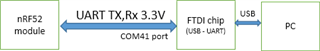
(1)HW setup is shown

(2Procedure
We have referred to the link below and the example.py scripts. Below are the steps we have followed before we ran the python scripts
(3)BT module was flashed with the DTM firmware “2020_05_08_BLSD_DTM_CT40_V2.hex” along with serial# and MAC addresses.
Please let us know if we are missing any other step/config to put the device into DTM mode as we are reusing the hex files from another project.
What would be the SDK version that must be used for DTM tests in case we don't have the SDK which was originally used to generate the hex files?
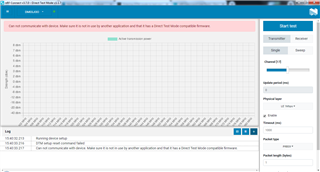
(4)We have run the example.py  script on the PC with the DUT com port field updated to COM41.
We did not observe any UART transactions from PC when scripts were run. HW connections for the COM41 port were verified physically by looping TX to RX and it works fine.
(a)Can you please share the example code ( python script ) used in the factory to test constant_carrier-continuous TX power measurement?
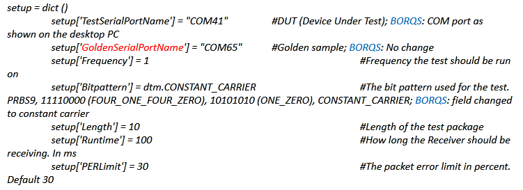
(b)What is the value to be updated in ‘'GoldenSerialPortName'’ in the example.py code snippet shared below

Best Regards

Mahesh HM

  • Hi,


    The python script that is supplied with nAN-34 is bluetooth v4.0 only, and written in python 2.7. It is unfortunately not updated in quite some time.

    It requires that you have two kits connected, both programmed with "direct_test_mode" firmware.

    BT module was flashed with the DTM firmware “2020_05_08_BLSD_DTM_CT40_V2.hex” along with serial# and MAC addresses.

     I am not aware of which DTM firmware this is, but you can look at the nRF5 SDK, examples/dtm/direct_test_mode/, for the standalone firmware for the nRF52840 (pca10056 board).


    I setup a quick test which sets up the DUT with constant carrier via this script, where it runs for 5 seconds:

    # Copyright (c) 2013 Nordic Semiconductor. All Rights Reserved.
    #
    # The information contained herein is property of Nordic Semiconductor ASA.
    # Terms and conditions of usage are described in detail in NORDIC
    # SEMICONDUCTOR STANDARD SOFTWARE LICENSE AGREEMENT.
    #
    # Licensees are granted free, non-transferable use of the information. NO
    # WARRANTY of ANY KIND is provided. This heading must NOT be removed from
    # the file.
    
    import dtm
    
    def main():
    	#General setup
    	setup = dict ()
    	setup['TestSerialPortName'] = "COMx"	#DUT (Device Under Test)
    	setup['GoldenSerialPortName'] = "COMy"	#Golden sample
    	setup['Frequency'] = 1					#Frequency the test should be run on
    	setup['Bitpattern'] = dtm.CONSTANT_CARRIER			#The bit pattern used for the test. PRBS9, 11110000 (FOUR_ONE_FOUR_ZERO), 10101010 (ONE_ZERO), CONSTANT_CARRIER
    	setup['Length'] = 20					#Length of the test package
    	setup['Runtime'] = 5000					#How long the Receiver should be receiving. In ms
    	setup['PERLimit'] = 30					#The packet error limit in percent. Default 30
    	
    	#Run tests on a single channel
    	print("Running tests on channel 1")
    	dtmObject = dtm.DTM(setup)
    	try:
    		dtmObject.runTransmitterTest()
    	except dtm.DTMError as error:
    		print(error.errormessage())
    	
    	del dtmObject
    
    if __name__ == '__main__':
        main()


    This is the current profile of the DUT:


    Note that you can also setup your test in nRF connect for desktop -> direct test mode application, and look at the log file to see the raw byte communication going back-and-forth.


    You can also look at the radio_test example in nRF5 SDK to evaluate the RF PHY.


    Kind regards,

    Håkon

  • Hi

    Thanks for sharing the information.

    As we currently don't have the nRF dev kit with us. Can you please let us know how to check the 2nd BLE with the setup shared earlier. I believe these are the steps which can be followed

    (1) Flash the DTM firmware to the nRF as suggested by you

    (2) Access nRF UART from a PC ( with out dev kit ) and send commands from nRF connect app in DTM mode (GUI). Please let us know there is no dependency between DTM firmware and nRF connect app ( or let us know the version of nRF connect app to be used)

    (3)Observe the TX power on a spectrum analyser

    Please let us know if this is feasible, this would help is to check the conducted TX power from the BLE module and verifies our RF front end.

    Let us know if I have missed any other step/ configuration

    RegardsM

    MaheshHM

  • Hi,


    MaheshHM said:

    Thanks for sharing the information.

    As we currently don't have the nRF dev kit with us. Can you please let us know how to check the 2nd BLE with the setup shared earlier. I believe these are the steps which can be followed

    (1) Flash the DTM firmware to the nRF as suggested by you

    (2) Access nRF UART from a PC ( with out dev kit ) and send commands from nRF connect app in DTM mode (GUI). Please let us know there is no dependency between DTM firmware and nRF connect app ( or let us know the version of nRF connect app to be used)

    (3)Observe the TX power on a spectrum analyser

    Please let us know if this is feasible, this would help is to check the conducted TX power from the BLE module and verifies our RF front end.

    Let us know if I have missed any other step/ configuration

    With those steps, and a properly connected uart interface, you should be able to setup the device in constant carrier with nRF Connect application direct test mode.

    Note that you might have to modify the example if you do not have your uart interface routed via P0.06 and P0.08 (which are the default pins in the board). This modification can be done in direct_test_mode/main.c


    Kind regards,

    Håkon

  • Hi

    I tried 'direct_test_mode_pca10056.hex' in the path suggested by you from the nRF5_SDK_15.0.0.

    I think the UART pins are not correctly configured in this Hex file as I see no activity on the UART TX line (PC->nRF)

    P1.04 Pin-H1 is the UART TX (out direction)

    P1.07 Pin-G1 is the UART RX (in direction)

    From the main.c

    I can see that we need to configure the UART TX and RX. can you please share an example / hex file with about pins configured as TX and RX?

    static void uart_init(void)
    {
    uint32_t err_code;
    const app_uart_comm_params_t comm_params =
    {
    RX_PIN_NUMBER,
    TX_PIN_NUMBER,
    RTS_PIN_NUMBER,
    CTS_PIN_NUMBER,
    APP_UART_FLOW_CONTROL_DISABLED,
    false,
    DTM_BITRATE
    };

  • Hi,


    MaheshHM said:

    P1.04 Pin-H1 is the UART TX (out direction)

    P1.07 Pin-G1 is the UART RX (in direction)

    The init routine reflects what should be written to the PSEL register:

    https://infocenter.nordicsemi.com/topic/ps_nrf52840/uarte.html?cp=4_0_0_5_33_8_25#register.PSEL.RXD


    For P1.04, you should write 32+4 = 36.

    For P1.07, you should write 32+7 = 39.


    Then recompile and flash your board, and try to connect again in the direct test mode PC application.


    Kind regards,

    Håkon 

Related