This post is older than 2 years and might not be relevant anymore
More Info: Consider searching for newer posts

how to interface external MCU host viaUART interface with nrf9160, with only 3 pins from UART (RD,TX,GND)

We would like to use nRF9160 has MODEM only feature, such that MCU in our product can talk to nRF9160 via UART interface.

We have found an sample application [Serial LTE Modem] that comes with nRFConnect SDK , we would need to use this application with following constraint

We have UART TX , UART RX and GND ( 3 signals ) and do not have provision for CTS/RTS or any other additional GPIO for interface MODEM(nRF9160) and our UART I/O signal TTL level is 3.3V

Is this possible to accomplish the same with the sample application [Serial LTE Modem]. 

External Com port ( 115200 bps, 8N1) , 

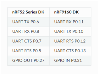
Pin connection between nrf9160 and 3.3v ttl-uart-usb cable connected to pc

 1. ( P0.11(RX) to usb to TTL cable (TX))

2. (P0.10(TX) to usb to TTL cable (RX))

3. Common ground 

In serial lte modem app .proj file modified to enable  Uart2 based macros and disabled the UART 0 based macro.

Note: I/O switch is kept at 3.3v side

Still couldn't get response for AT commands.

Please let me know is there is a steps to configure UART 2 with no flow control and no additional gpio .

I am using segger embedded studio.

With Best Regards,

Ilanchezhian T

Parents
  • Thanks for the response. 

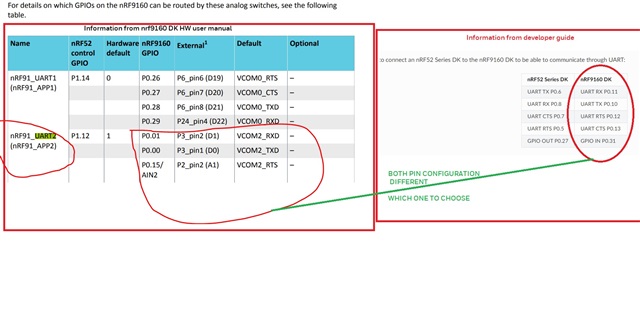
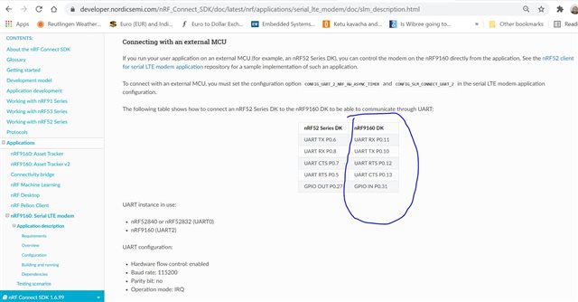
    1. I could see the different information ( mentioned in nRF9160 DK HW manual and application description in developer guide) regarding the UART2 pins of the nrF9160. Which one is correct I am really confused. 

    nrF9160 DK connection diagram

    Different infomation in DK user guide and developer guide regarding UART2 connection with nrF9160

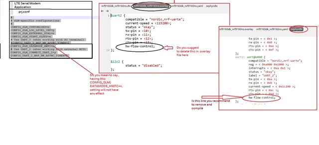
    2.regarding the settings to be touched I have taken a screen shot, could you provide your feedback for the same. 

    Project setting and configuration details

    3. As I am new to embedded linux based development, I do not really understand how feature configuration and pin configuration works in the form of .dts, .dtsoverlay, menuconfig and prj.conf. Please let me know the proper steps to configure and use application processors UART2 of nRF9160 in 2 pin mode. My end objective is to interface my external MCU host via UART interface to communicate via UART I/F with nrF9160 modem via AT commands.

    Thanks 

    Ilanchezhian T

  • 1.a) This approach should be fine. Just make sure the voltages are correct. It could be a good idea to measure the voltages from the USB-232-3V3 cable to see if they infact are 3V3. Have you checked this communication with a scope? Also remember to set up nRF9160 DK for 3V3 communication. You can set the VDD voltage to 3V0 with SW9, however, you probably need to go to 3V3. This can be done by customizing the DK's voltage level. If you apply 3V3 to VIO_REF(P20) then the GPIO voltages should be adjusted automatically. 

    Ilanchezhian T said:
    3) What are pins present in nRF9160-DK can be used to have external UART interface with host microcontroller

     3) You may choose any pin that is not already in use. I could get back to you with a few examples. 

    Answers to the rest of your questions will follow later today. 

    Best regards,

    Håkon

  • Ilanchezhian T said:
    4) Our microcontroller I/O line is 3.3V does the nRF9160 supports 3.3V on its I/O line

     4) Yes. As mentioned above, make sure to configure nRF9160 accordingly.  

    Ilanchezhian T said:
    6) In our custom hardware , to flash the nrf9160 modem software and its MCU for applications, What are the additional circuitry required other than the uart I/F connections, VCC and GND ?

     6) You will need the 10-pin programming interface in Table 1. Does your board have tight pcb area constraints? If that case, you could convert this to a 6-pin interface. The board will  in any case need to have it's own supply as this is not supplied through the programming interface.  

    Ilanchezhian T said:
    6.a) I think we need usb and jlink circuitry, please provide your input in this regard

    6.a) Sorry, I am not sure exactly what you are asking for. Could you please explain? 

  • Ilanchezhian T said:
    5) We might need to develop the custom hardware that gets plugged into our product, How easy is to customize the "LTE Serial Modem" software available as part of nrf9160 SDK

    It sounds like changing a few configs and device tree properties will allow you to run the application on a custom board. We are not testing the applications in all possible combinations of configurations, so you would need to perform tests, like any project.  

    Ilanchezhian T said:
    5.a) If it is very simple only in terms of configurations please provide us some steps to perform this

    This should be feasible. Going through the application description and the section on Connecting with an external MCU should get you started. I will be back with more details.

    One approach, as you are moving forward, might be to demonstrate the setup using an nRF 52 series DK. This setup has been tested, and it allows you to get familiar with the functionality. 

    Please also read the section Extending the application

  • 6.a) Question is - Do we need to have  similar hardware circuitry as present in nRF9160 DK ( usb connector and debugger circuitry) in our product in order to code flashing in both Modem Processor and Application Processor.

  • 6.a) Thank you for the clarification. In order to program the nRF9160 SiP you only need the programming interface mentioned as a reply to 6). 

Reply Children
Related