This post is older than 2 years and might not be relevant anymore
More Info: Consider searching for newer posts

how to interface external MCU host viaUART interface with nrf9160, with only 3 pins from UART (RD,TX,GND)

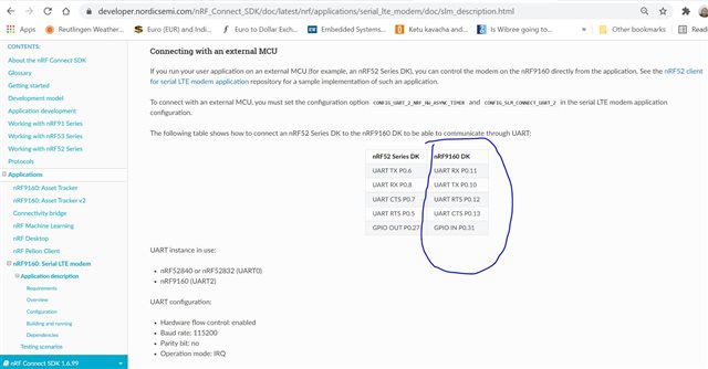
We would like to use nRF9160 has MODEM only feature, such that MCU in our product can talk to nRF9160 via UART interface.

We have found an sample application [Serial LTE Modem] that comes with nRFConnect SDK , we would need to use this application with following constraint

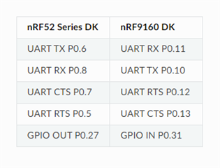
We have UART TX , UART RX and GND ( 3 signals ) and do not have provision for CTS/RTS or any other additional GPIO for interface MODEM(nRF9160) and our UART I/O signal TTL level is 3.3V

Is this possible to accomplish the same with the sample application [Serial LTE Modem]. 

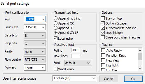
External Com port ( 115200 bps, 8N1) , 

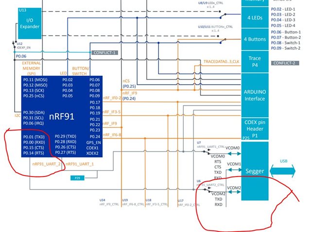
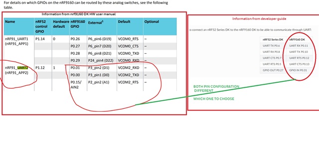
Pin connection between nrf9160 and 3.3v ttl-uart-usb cable connected to pc

 1. ( P0.11(RX) to usb to TTL cable (TX))

2. (P0.10(TX) to usb to TTL cable (RX))

3. Common ground 

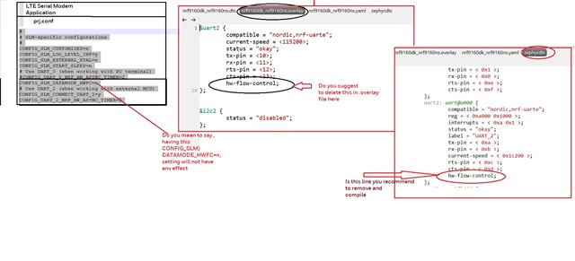
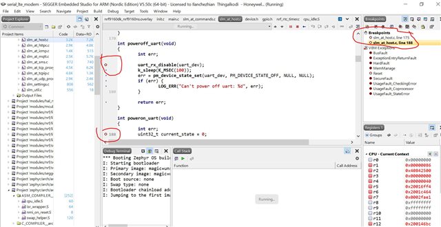
In serial lte modem app .proj file modified to enable  Uart2 based macros and disabled the UART 0 based macro.

Note: I/O switch is kept at 3.3v side

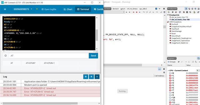
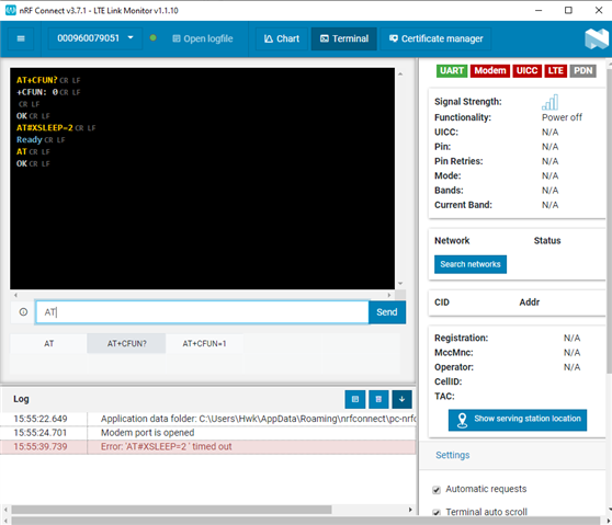
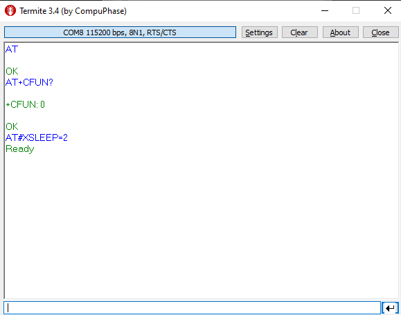
Still couldn't get response for AT commands.

Please let me know is there is a steps to configure UART 2 with no flow control and no additional gpio .

I am using segger embedded studio.

With Best Regards,

Ilanchezhian T

Parents
  • Hi

    Take a look at this case and let me know how it goes.

    Disable HWFC in serial modem application

    Best regards,

    Håkon

  • Thanks for the response. 

    1. I could see the different information ( mentioned in nRF9160 DK HW manual and application description in developer guide) regarding the UART2 pins of the nrF9160. Which one is correct I am really confused. 

    nrF9160 DK connection diagram

    Different infomation in DK user guide and developer guide regarding UART2 connection with nrF9160

    2.regarding the settings to be touched I have taken a screen shot, could you provide your feedback for the same. 

    Project setting and configuration details

    3. As I am new to embedded linux based development, I do not really understand how feature configuration and pin configuration works in the form of .dts, .dtsoverlay, menuconfig and prj.conf. Please let me know the proper steps to configure and use application processors UART2 of nRF9160 in 2 pin mode. My end objective is to interface my external MCU host via UART interface to communicate via UART I/F with nrF9160 modem via AT commands.

    Thanks 

    Ilanchezhian T

  • Ilanchezhian T said:
    5) We might need to develop the custom hardware that gets plugged into our product, How easy is to customize the "LTE Serial Modem" software available as part of nrf9160 SDK

    It sounds like changing a few configs and device tree properties will allow you to run the application on a custom board. We are not testing the applications in all possible combinations of configurations, so you would need to perform tests, like any project.  

    Ilanchezhian T said:
    5.a) If it is very simple only in terms of configurations please provide us some steps to perform this

    This should be feasible. Going through the application description and the section on Connecting with an external MCU should get you started. I will be back with more details.

    One approach, as you are moving forward, might be to demonstrate the setup using an nRF 52 series DK. This setup has been tested, and it allows you to get familiar with the functionality. 

    Please also read the section Extending the application

  • 6.a) Question is - Do we need to have  similar hardware circuitry as present in nRF9160 DK ( usb connector and debugger circuitry) in our product in order to code flashing in both Modem Processor and Application Processor.

  • 6.a) Thank you for the clarification. In order to program the nRF9160 SiP you only need the programming interface mentioned as a reply to 6). 

  • Ilanchezhian T said:
    2) What are the necessary UART pins required ( As per the application note we have seen that 5 pins (RTS,CTS,RX,TX,GPIO) are mentioned,
    I think GND pin is also required as the uart signals are not differential signals)

    2) Normally, only the three connections RX, TX and ground are needed for UART to work without flow control. I have not yet been able to confirm whether someone has tested disabling this with serial_lte_modem, specifically. 

    Ilanchezhian T said:
    2.a) If all the pins are not required ( then RX,TX,GND) is ok to establish connection between modem and our host microcontroller

    2.a) The serial_lte_modem has a config option, CONFIG_SLM_INTERFACE_PIN - Interface GPIO to wake up or exit idle mode, for setting up an additional GPIO between nRF9160 and the external MCU. This GPIO seems to be used for exiting nRF9160 from IDLE or sleep. If you have another way to wake up nRF9160, then only RX, TX and GND are needed between the two devices. 


  • 2.a) Using the GPIO is the recommended way to go. If saving one pin is important, you may leave the peripheral running while the application is sleeping. This would add an extra ~0.5 mA. 

Reply
  • 2.a) Using the GPIO is the recommended way to go. If saving one pin is important, you may leave the peripheral running while the application is sleeping. This would add an extra ~0.5 mA. 

Children
  • I am still to explore on this  GPIO. But have few queries regarding this

    1. How does the MCU host gets indicated that nRF9160 is in idle or sleep state. 

    2. When do we need to activate this GPIO to save power, For example my use case is that  let's say during host powered ON , it sends set of  AT commands initially to  connect to network with say eDRX and PSM mode enabled/disabled. And then host application is sending the data to the external devices  every 5 mins once.

  • 1. Assume that the modem and application on nRF9160 normally takes responsibility for sleeping whenever there is nothing to do. 

    2. Please refer to Power saving #XSLEEP. #XSLEEP has three options, so the host may put nRF9160 to idle, sleep, or only put the UART to sleep.

    • When the host MCU wants to wake up the UART, use the GPIO.
    • When the host MCU wants to turn off the UART, send AT#XSLEEP=2 to put the UART only to sleep.

    The UART consumes around 700µA so it should be put to sleep whenever possible. After eDRX/PSM is requested, it is important to verify that this is accepted by the network. XMODEMSLEEP is useful for synchronizing sleep and wake-ups when optimizing power consumption. 

  • Hi Helsing, I am trying to put UART in sleep mode  using AT#XSLEEP=2.  I could see that If I put breakpoint  uart power on and uart powerOFF function  of SLM sample application this features works and if I remove the breakpoint is  not working. 

    My Observation: 

    UART 0 is enabled and UART2 is disabled 

    Breakpoint is placed at uart power on() and uart power off() function 

    provide the command AT#XSLEEP=2, break point hit in uart power off () function , run the progam

    Pressed Button 0 in the nrf9160 board , break point hit on the uart power on () function , run the program

    provide Any uart command it works 

    BUT IF I REMOVE the breakpoints and do the same it is not working as expected , in fact nothing happens, what is that i am doing wrong. 

    Please find the Link monitor terminal logs and screen shots attached for further investigation.  break points

    1
    2
    3
    4
    5
    6
    7
    8
    9
    10
    11
    12
    13
    14
    15
    16
    17
    18
    19
    2021-09-22T15:03:41.181Z INFO Application data folder: C:\Users\h438415\AppData\Roaming\nrfconnect\pc-nrfconnect-linkmonitor
    2021-09-22T15:03:41.220Z DEBUG App pc-nrfconnect-linkmonitor v1.1.10 official
    2021-09-22T15:03:41.221Z DEBUG App path: C:\Users\h438415\.nrfconnect-apps\node_modules\pc-nrfconnect-linkmonitor
    2021-09-22T15:03:41.221Z DEBUG nRFConnect 3.7.0, required by the app is (^3.6.0)
    2021-09-22T15:03:41.221Z DEBUG nRFConnect path: C:\Users\h438415\AppData\Local\Programs\nrfconnect\resources\app.asar
    2021-09-22T15:03:41.221Z DEBUG HomeDir: C:\Users\h438415
    2021-09-22T15:03:41.221Z DEBUG TmpDir: C:\Users\h438415\AppData\Local\Temp
    2021-09-22T15:03:43.584Z INFO Modem port is opened
    2021-09-22T15:03:43.593Z DEBUG modem >> AT+CFUN?
    2021-09-22T15:03:43.623Z DEBUG modem << +CFUN: 0
    2021-09-22T15:03:43.626Z DEBUG modem << OK
    2021-09-22T15:04:05.402Z DEBUG modem >> AT+CGDCONT=0,"IP","default"
    2021-09-22T15:04:05.418Z DEBUG modem << OK
    2021-09-22T15:04:10.754Z DEBUG modem >> AT+CFUN=1
    2021-09-22T15:04:10.797Z DEBUG modem << OK
    2021-09-22T15:04:26.826Z DEBUG modem >> AT+CGPADDR=0
    2021-09-22T15:04:26.841Z DEBUG modem << +CGPADDR: 0,"192.168.2.26"
    2021-09-22T15:04:26.845Z DEBUG modem << OK
    2021-09-22T15:04:41.979Z DEBUG modem >> AT#XSLEEP=2
    XXXXXXXXXXXXXXXXXXXXXXXXXXXXXXXXXXXXXXXXXXXXXXXXXX

    Thanks  

    Ilan 

  • Hi Ilan,

    Have you made any modifications to SLM? Have you enabled any configs or implemented the changes related to disabling flow control?

    I am not seeing this when I am testing SLM myself. I tested without any breakpoints, and when I press the button, I can see 'Ready' appear in LTE Link Monitor:

    Would you be able to share your project files?

    Best regards,

    Håkon

  • Hi again,

    It looks like I have been able to reproduce this, and we might have a workaround.

    Ilanchezhian T said:
    BUT IF I REMOVE the breakpoints and do the same it is not working as expected , in fact nothing happens, what is that i am doing wrong. 

    Exactly what is not working? Is the board not waking up? Are you able to send more AT commands? If you are not able to send anything it could be that LTE Link Monitor is failing.

    I have been able to reproduce similar behavior where LTE Link Monitor stops working after the breakpoints are removed.

    Could you please try debugging the board without LTE Link Monitor and switch to a dedicated serial output terminal? Here are the settings that worked on my side. Please note that you might need to select a different COM-port on your side. I have flow control enabled as I am using SLM out of the box.

    Below shows the use of AT#XSLEEP=2 and wake up by button.

    Please let me know if this works on your side. Is this a satisfying workaround at this stage? The issue you reported is is possibly a corner case related to LTE Link Monitory. Hopefully, you should be able to used LTE Link Monitor going forward with your project.