NRF52840 QSPI IFTIMING Problem

Dear,

We are working on our custom boards to develop a watch product which need external flash memory connected by QSPI interface. In this product, the UI images and font bitmaps store in the external memory. We found the screen of some watch samples display noise content(the data source comes from the external flash memory).  We tried to change IFTIMING register value, and we found the problem watches display problem been fixed. But some other watches no need to change the default value of IFTIMING (the default whole register value 0x00000200). The proportion of problem products is about 6%. 
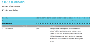
We want to know why the problem products can fix this issue by change IFTIMING register while some most of the product (the other 96%) no need to change this register. And whether the IFTIMING register change would lead other unknown issues.

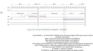
The following is my understanding about IFTIMING, seems the default value is not fit the the CLOCK mode=0 (CPOL=0, CPHA=0) with the QSPI clock=32MHz.
Our the external flash memory is XT25F128BWOIGT.

  • I also encountered this problem during production. The strange thing is that after I replaced the new 52840 chip, its read and write errors disappeared, but the wrong chip still continues to read and write errors. I haven't changed any registers, or it is normal if I change the frequency to 16MHZ? Is it due to the differences in the chip itself?

  • We want to know why the problem products can fix this issue by change IFTIMING register while some most of the product (the other 96%) no need to change this register. And whether the IFTIMING register change would lead other unknown issues.

    I don't know why you see this issue exactly. I suggest we do a HW review to see if there is any obvious signal integrity issues in the design. 
    We don't know if changing the timings will lead to unknow problems in your design. 

    If you change the IFTIMING of the 'good' devices, does it have a negative impact, or do they continue to function as intended?

  • In both cases (Bing and Youcan) it can be the result of ESD damage. A blown ESD fuse on one of the SPI pins will cause signal integrity issues. 

    But I think it's more likely an issue with the HW design, poor grounding will lead signal intergrity issues. 

    The device-to-device variation from our factory is insignificant. In order to make these variations significant there must be another factor like ESD issue during manufacturing or a spesific GND issue in the design. 

  • We tested a batch of "bad" devices and changed the IFTIMING register to 0x100. Most of the read and write data damage can be recovered, but some of them cannot be solved, but these can be solved by reducing the frequency to 16MHZ.

  • We tested a batch of machines after changing IFTIMING, and did not find any adverse effects on the use, or it may be that our testing time is relatively short. But this QSPI, we are directly connected to the MCU, there are no additional devices in between , But I did not use the pins recommended by NORDIC, we used the QSPI pins as follows:

    //flash	
    #define GPIO_FLASH_MOSI				GPIO1_10	//IO0
    #define GPIO_FLASH_MISO				GPIO1_14	//IO1
    #define GPIO_FLASH_SCLK				GPIO1_11
    #define GPIO_FLASH_CS				GPIO1_15
    	
    #define GPIO_FLASH_WP				GPIO1_13	//IO2
    #define GPIO_FLASH_HOLD				GPIO1_12	//IO3

Related