
I am trying to use the NRF52832 to connect to the BMA456 Accelerometer from Bosch using SPI and am running into the following issue:
- All read/write commands work fine except for the burst write of the configuration file.
- I decoded every single SPI transfer to the sensor while the configuration file was being written (in chunks of 16 Bytes) and have only noticed the following behavior (which I honestly don't know if it is normal or not): after some packets the MOSI line remains HIGH, and some others it goes LOW, without a noticeable pattern.
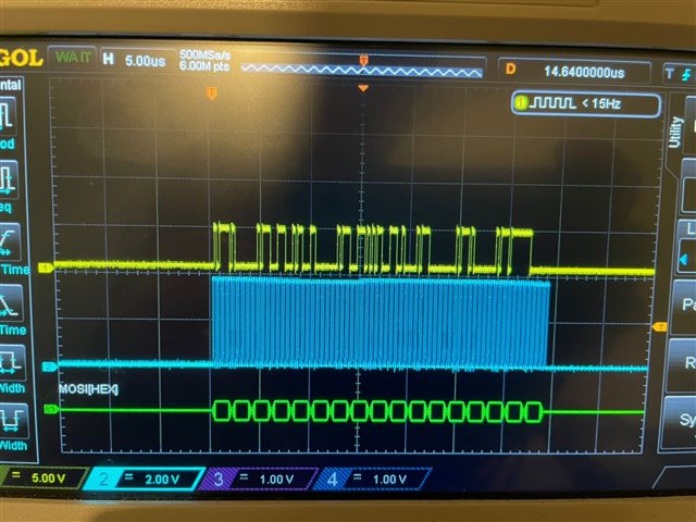
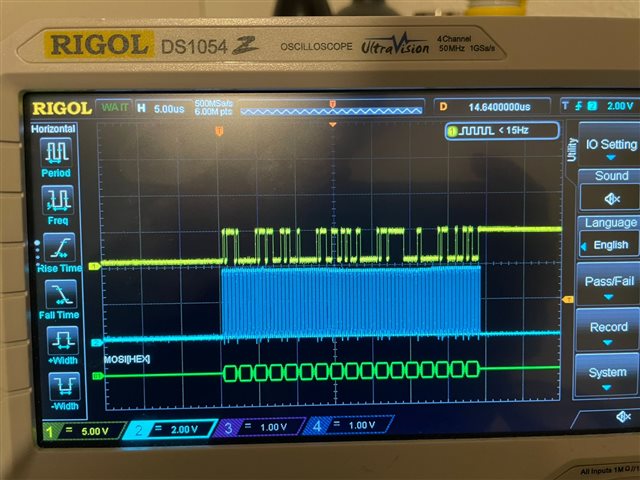
From a first glance, the entire config file seems to be written, but clearly, something is going wrong during the process and I haven't been able to debug it on my own so far.
Other hypotheses I eliminated:
- faulty sensor hardware: the sensor works fine with an Arduino so that's not it
- an error in the board design/wiring of the NRF52 on my board: the SPI bus works well with other sensors on the board
I've been tracking the issue and apparently, others have had the same problem with I2C and other Bosch sensors (like the BMI270), but I still don't know how to fix it.
Code:
- I am using the latest NRF5 SDK (v17)
- Bosch API: https://github.com/BoschSensortec/BMA456-Sensor-API
- SPI read and write functions
#include "TapID_spi.h"
#include "nrf_delay.h"
#include "nrf_gpio.h"
#include "nrf_drv_spi.h"
#include "nrf_log.h"
const nrf_drv_spi_t spi_instance = NRF_DRV_SPI_INSTANCE(SPI_INSTANCE); /**< SPI instance. */
static volatile bool spi_xfer_done;
/**
* @brief SPI user event handler.
* @param event
*/
void spi_event_handler(nrf_drv_spi_evt_t const * p_event,
void * p_context)
{
spi_xfer_done = true;
NRF_LOG_INFO("Transfer completed.");
}
/*!
* @brief Function for initialization of SPI bus.
*/
int8_t spi_init(uint8_t cs_pin)
{
ret_code_t ret;
nrf_drv_spi_config_t spi_config = NRF_DRV_SPI_DEFAULT_CONFIG;
spi_config.frequency = NRF_DRV_SPI_FREQ_4M;
spi_config.mode = NRF_DRV_SPI_MODE_0;
spi_config.ss_pin = cs_pin;
spi_config.miso_pin = SPI_MISO_PIN;
spi_config.mosi_pin = SPI_MOSI_PIN;
spi_config.sck_pin = SPI_SCK_PIN;
spi_config.orc = 0xFF;
spi_config.bit_order = NRF_DRV_SPI_BIT_ORDER_MSB_FIRST;
ret = nrf_drv_spi_init(&spi_instance, &spi_config, spi_event_handler, NULL);
return (int8_t)ret;
}
void spi_uninit()
{
nrf_drv_spi_uninit(&spi_instance);
}
/**
* @brief Generic SPI read function.
* @param cs_pin : chip select pin of the target slave
* @param reg_addr: target register address
* @param reg_data: pointer to the data register
* @param length: target data length
*/
int8_t spi_read(uint8_t cs_pin, uint8_t reg_addr, uint8_t *reg_data, uint8_t length)
{
ret_code_t ret;
spi_xfer_done = false;
ret = nrf_drv_spi_transfer(&spi_instance, ®_addr, 1, reg_data, length);
while(!spi_xfer_done)
{
__WFE();
}
return ret;
}
int8_t spi_write(uint8_t cs_pin, uint8_t reg_addr, uint8_t *reg_data, uint8_t length)
{
ret_code_t ret;
uint8_t temp_buff[length +1];
temp_buff[0]=reg_addr;
memcpy(&temp_buff[1], reg_data, length);
spi_xfer_done = false;
ret = nrf_drv_spi_transfer(&spi_instance, temp_buff, length+1, NULL, 0);
while(!spi_xfer_done)
{
__WFE();
}
return ret;
}
- config file:
08641.sdk_config.h
main file:
/**
 * Copyright (c) 2014 - 2020, Nordic Semiconductor ASA
 *
 * All rights reserved.
 *
 * Redistribution and use in source and binary forms, with or without modification,
 * are permitted provided that the following conditions are met:
 *
 * 1. Redistributions of source code must retain the above copyright notice, this
 *    list of conditions and the following disclaimer.
 *
 * 2. Redistributions in binary form, except as embedded into a Nordic
 *    Semiconductor ASA integrated circuit in a product or a software update for
 *    such product, must reproduce the above copyright notice, this list of
 *    conditions and the following disclaimer in the documentation and/or other
 *    materials provided with the distribution.
 *
 * 3. Neither the name of Nordic Semiconductor ASA nor the names of its
 *    contributors may be used to endorse or promote products derived from this
 *    software without specific prior written permission.
 *
 * 4. This software, with or without modification, must only be used with a
 *    Nordic Semiconductor ASA integrated circuit.
 *
 * 5. Any software provided in binary form under this license must not be reverse
 *    engineered, decompiled, modified and/or disassembled.
 *
 * THIS SOFTWARE IS PROVIDED BY NORDIC SEMICONDUCTOR ASA "AS IS" AND ANY EXPRESS
 * OR IMPLIED WARRANTIES, INCLUDING, BUT NOT LIMITED TO, THE IMPLIED WARRANTIES
 * OF MERCHANTABILITY, NONINFRINGEMENT, AND FITNESS FOR A PARTICULAR PURPOSE ARE
 * DISCLAIMED. IN NO EVENT SHALL NORDIC SEMICONDUCTOR ASA OR CONTRIBUTORS BE
 * LIABLE FOR ANY DIRECT, INDIRECT, INCIDENTAL, SPECIAL, EXEMPLARY, OR
 * CONSEQUENTIAL DAMAGES (INCLUDING, BUT NOT LIMITED TO, PROCUREMENT OF SUBSTITUTE
 * GOODS OR SERVICES; LOSS OF USE, DATA, OR PROFITS; OR BUSINESS INTERRUPTION)
 * HOWEVER CAUSED AND ON ANY THEORY OF LIABILITY, WHETHER IN CONTRACT, STRICT
 * LIABILITY, OR TORT (INCLUDING NEGLIGENCE OR OTHERWISE) ARISING IN ANY WAY OUT
 * OF THE USE OF THIS SOFTWARE, EVEN IF ADVISED OF THE POSSIBILITY OF SUCH DAMAGE.
 *
 */
/** @file
 *
 * @defgroup ble_sdk_uart_over_ble_main main.c
 * @{
 * @ingroup  ble_sdk_app_nus_eval
 * @brief    UART over BLE application main file.
 *
 * This file contains the source code for a sample application that uses the Nordic UART service.
 * This application uses the @ref srvlib_conn_params module.
 */

#include <stdbool.h>
#include <stdint.h>
#include <string.h>
#include <stdio.h>
#include <math.h>
#include "nordic_common.h"
#include "nrf.h"
#include "nrf_sdh_soc.h"
#include "app_error.h"
#include "app_uart.h"
#include "app_timer.h"
#include "app_button.h"
#include "app_util_platform.h"
#include "ble_nus.h"
#include "nrf_pwr_mgmt.h"
#include "custom_board.h"
#include "nrf_drv_timer.h"
#include "nrf_drv_gpiote.h"
#include "nrf_drv_clock.h"
#include "nrf_queue.h"

#if defined (UART_PRESENT)
#include "nrf_uart.h"
#endif
#if defined (UARTE_PRESENT)
#include "nrf_uarte.h"
#endif

#include "nrf_log.h"
#include "nrf_log_ctrl.h"
#include "nrf_log_default_backends.h"
#include "nrf_delay.h"

#include "TapID_ble.h"
#include "TapID_bma456.h"

#define APP_TIMER_PRESCALER             0                                           /**< Value of the RTC1 PRESCALER register. */
#define APP_TIMER_OP_QUEUE_SIZE         4                                           /**< Size of timer operation queues. */

#define UART_TX_BUF_SIZE                256                                         /**< UART TX buffer size. */
#define UART_RX_BUF_SIZE                256                                         /**< UART RX buffer size. */

#define IMU_QUEUE_SIZE           5


// #define IMU_SAMPLE_TIMER_INTERVAL     APP_TIMER_TICKS(100)     // 100 ms intervals
// APP_TIMER_DEF(imu_sample_timer_id);

unsigned char str_imu[30];
//circular buffer to store sensor data before running average filter
//the queue will overflow when it is full

extern volatile bool connected_flag;
#define USE_IMU0
// #define USE_IMU1

// flag to check if UART is enabled or disabled.
volatile bool uart_enabled = false;
// flag for the button state
static volatile bool button_state = false;
// IMU data ready flag
static volatile bool new_data_ready = false;

//floats to store the filtered sensor data
float _ax, _ay, _az;
struct bma4_accel sens_data = { 0 };
static struct bma4_dev imu0 = {0, .cs_pin  = SPI_SS0_PIN};


// /**@brief  Function for initializing the UART module.
//  */
// /**@snippet [UART Initialization] */
static void uart_init(void)
{
    uint32_t                     err_code;
    app_uart_comm_params_t const comm_params =
    {
        .rx_pin_no    = RX_PIN_NUMBER,
        .tx_pin_no    = TX_PIN_NUMBER,
        .rts_pin_no   = RTS_PIN_NUMBER,
        .cts_pin_no   = CTS_PIN_NUMBER,
        .flow_control = APP_UART_FLOW_CONTROL_DISABLED,
        .use_parity   = false,
#if defined (UART_PRESENT)
        .baud_rate    = NRF_UART_BAUDRATE_115200
#else
        .baud_rate    = NRF_UARTE_BAUDRATE_115200
#endif
    };

    APP_UART_FIFO_INIT(&comm_params,
                       UART_RX_BUF_SIZE,
                       UART_TX_BUF_SIZE,
                       uart_event_handle,
                       APP_IRQ_PRIORITY_LOWEST,
                       err_code);
    APP_ERROR_CHECK(err_code);

    // UART enabled
    uart_enabled = true;
}
/**@snippet [UART Initialization] */


/**@brief Function for initializing the nrf log module.
 */
static void log_init(void)
{
    ret_code_t err_code = NRF_LOG_INIT(NULL);
    APP_ERROR_CHECK(err_code);

    NRF_LOG_DEFAULT_BACKENDS_INIT();
}
/**@brief Function for initializing the timer module.
 */
static void timers_init(void)
{
    ret_code_t err_code = app_timer_init();
    APP_ERROR_CHECK(err_code);

    // err_code = app_timer_create(&imu_sample_timer_id, APP_TIMER_MODE_REPEATED, timer_timeout_sensor_handler);
    // APP_ERROR_CHECK(err_code);
}

/**@brief Function for initializing power management.
 */
static void power_management_init(void)
{
    ret_code_t err_code;
    err_code = nrf_pwr_mgmt_init();
    APP_ERROR_CHECK(err_code);
}

/**
 * @brief Function for initializing the Top side LEDs
 * TODO: LEDs also refernce by BSP Library
 */
static void leds_init(){
    nrf_gpio_cfg_output (LED_0);
    nrf_gpio_cfg_output (LED_1);
    nrf_gpio_cfg_output (LED_2);
    nrf_gpio_cfg_output (LED_3);
    nrf_gpio_cfg_output (LED_4);

    nrf_gpio_pin_clear(LED_0);
    nrf_gpio_pin_clear(LED_1);
    nrf_gpio_pin_clear(LED_2);
    nrf_gpio_pin_clear(LED_3);
    nrf_gpio_pin_clear(LED_4);
}

void set_all_leds(){
    nrf_gpio_pin_set(LED_0);
    nrf_gpio_pin_set(LED_1);
    nrf_gpio_pin_set(LED_2);
    nrf_gpio_pin_set(LED_3);
    nrf_gpio_pin_set(LED_4);
}

void clear_all_leds(){
    nrf_gpio_pin_clear(LED_0);
    nrf_gpio_pin_clear(LED_1);
    nrf_gpio_pin_clear(LED_2);
    nrf_gpio_pin_clear(LED_3);
    nrf_gpio_pin_clear(LED_4);
}


/**@brief Application main function.
 */
int main(void)
{
    ret_code_t err_code;
    connected_flag = false;

    // Initialize.
    uart_init();
    log_init();
    timers_init();
    power_management_init();
    leds_init();
    TapID_ble_init();

    err_code = spi_init(SPI_SS0_PIN);
    if (err_code == NRF_SUCCESS){
        printf("SPI initialized\n");
    }

    #ifdef USE_IMU0
    err_code = bma456_imu_init(&imu0, false);
    if (err_code !=0){
        printf("Error intializing IMU\n");
    }else{
        printf("BMA456 initialized\n");
    }
    #endif

    // Enter main loop.
    for (;;)
    {
      //update sensor data
      err_code = bma4_read_accel_xyz(&sens_data, &imu0);
      bma4_error_codes_print_result("bma4_read_accel_xyz status",err_code);

      if (err_code == BMA4_OK){

      _ax = sens_data.x;
      _ay = sens_data.y;
      _az = sens_data.z;

      sprintf((char *)str_imu, "%.1f, %.1f, %.1f\n", (float)_ax, (float)_ay, (float)_az);

      if (connected_flag){
      send_data_ble(str_imu, sizeof(str_imu));
      printf("%f, %f,%f \n", _ax, _ay, _az);

      }
        nrf_delay_ms(5);
    }
  }
}

