Hi,
I faced the exact problem nda, here. I take step just like nda did before. I unchecked "Enable debug options" as Marte Myrvold told, but still the same problem.

OS: Windows 10
SDK: v1.8.0
TNX.
Hi,
I faced the exact problem nda, here. I take step just like nda did before. I unchecked "Enable debug options" as Marte Myrvold told, but still the same problem.
OS: Windows 10
SDK: v1.8.0
TNX.
Hi,
Does this happen only in VS Code?
Regards,
Priyanka
I've to admit I'm testing on a custom board not a nRF52840DK. E73-2G4M08S1C.
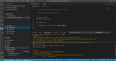
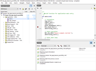
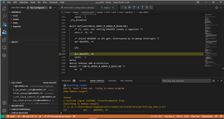
In different scenarios, I tested blinky sample from nRF5 SDK for Thread and Zigbee v4.1.0 for keil, after some challenges it worked. zigbee-v4-1-examples-not-working-with-keil. Then I decided try SEGGER embedded studio. The blinky example worked, but after I tried Bluetooth examples, I failed. The exact sample I tested is "ble_app_beacon_pca10056_s140" from nRF5 SDK for Thread and Zigbee v4.1.0. After debugging it turns out it
hangs on "ble_stack_init();" line and it doesn't go further
I have to notice that non of Zephyr's examples worked whether using VS Code or SEGGER embedded studio.
I have five years of experience in embedded world. I've working experience with ST, TI, Espressif, and AtmelAVR but I'm new to Nordic microcontrollers.
TNX
Hi again,
You Nordic guys are very kind and supportive.
These errors go after compilation. But I've noticed If I try to open <zephyr.h> it won't work. This happens for <devicetree.h> also. I have to say that I'm using VS Code to create application for windows, maybe a conflict in configuration. (Although it didn't work with SEGGER embedded studio either).
I have to purchase the nRF52840DK from China. These guys are in they're holidays  .
.
Would you please send me two hex file base on Zephyr RTOS?
One for toggling LED on P0.06 (just like nrf52840dongle) . And the other one, just a simple Bluetooth broadcaster.
At least I can verify the hardware setup. I'll flash these hex files using J-flash.
TNX

Hi,
I am sorry for the delayed response. Were you able to get the DK? If not I will send the hex files soon.
-Priyanka
That's OK.
Unfortunately no. I have to purchase from China and they are on their new year holidays.
TNX.
Hi,
Really sorry for the delayed response. I have attached a zip file of the build folder(which has the hex file) as well as the hex file separately. Hope this helps! 
Regards,
Priyanka
Hi Priyanka,
Now nrf52840dk is in my hand. The hex file and project you provided are working with no problem. I also tested other examples.
To flash the custom hardware, I used the debug output P20 from nrf52840dk:
VDD nRF -> VDD target
VDD nRF -> VTG
(These three pins are connected to each other)
SWDIO -> SWDIO
SWCLK -> SWCLK
GND DETECT -> gnd target
Again I faced the same error as I mentioned in the first message of this topic.
Then I tried the blinky example from nRF5 SDK for Thread and Zigbee v4.1.0 and it worked. So the wiring between custom board and the nrf52840dk is OK.
In the next step, I tried to flash the DK with the Zephyr's blinky hex file using Keil. In the DK it worked, but in the custom board it didn't. Then i decide to re-flash the custom board with nRF5 SDK for Thread and Zigbee v4.1.0 blinky project using Keil. It didn't work either UNLESS I erased the custom board using jflah. Then, flashing the custom board with nRF5 SDK for Thread and Zigbee v4.1.0 blinky project using Keil worked.
Next, I tried to flash another custom board (maybe the first custom board was damaged), I got the same result. I got back to my design, I realized the pull up resistor and capacitor for the RESET pin aren't soldered (some times that was the issue for not working AVRs) but it didn't help.
Maybe there is a problem with the module (maybe it's a fake one) or the nrf52840 chip. I realized the chip mounted on the DK is "NRF52840_xxAA_REV2" but on the module "NRF52840_xxAA" is mounted.
Do you have any idea?
I attach my PCB design, please evaluate it, maybe you find something.
TNX
Hi,
When you try to flash the Zephyr's blinky sample onto the custom board, what is the error message that you get.
-Priyanka