This discussion has been locked.
You can no longer post new replies to this discussion. If you have a question you can start a new discussion

Using UART1 for the serial communication

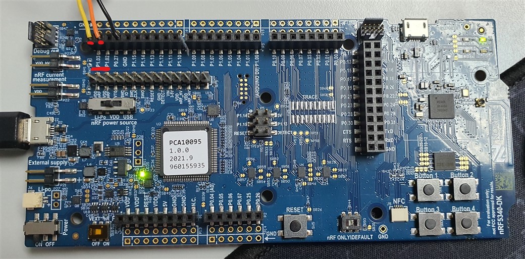
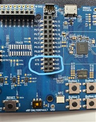
I am using nRF5340DK and would like to send and receive data to computer via UART1 and pins "TX", "RX", "CTS" and "RTS" using USB TO RS232 SERIAL CONVERTER.


This way I would keep UART0 for logging.

But I can't receive or send data via UART1.

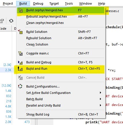
I'm using the Segger IDE and the Peripheral_UART for the first nRF5340 DK board and the Central_UART example for the second board.

Im trying to use UART1 in Peripheral_UART example.

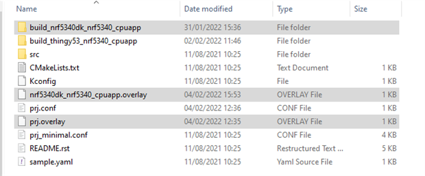
For now I changed settings for UART1 in zephyr.dst file

uart1: uart@9000 {
  compatible = "nordic,nrf-uarte";
  reg = < 0x9000 0x1000 >;
  interrupts = < 0x9 0x1 >;
  status = "okay";
  label = "UART_1";
  current-speed = < 0x4b00 >;
  tx-pin = < 0x21 >;
  rx-pin = < 0x20 >;
  rts-pin = < 0x0b >;
  cts-pin = < 0x0a >;
};

And i added in autoconfig.h

#define CONFIG_NRFX_UARTE1 1
#define CONFIG_UART_NRFX 1
#define CONFIG_UART_1_NRF_UARTE 1
#define CONFIG_UART_1_ENHANCED_POLL_OUT 1
#define CONFIG_UART_1_ASYNC 1
#define CONFIG_UART_1_NRF_TX_BUFFER_SIZE 32

It won't work with UART1.

When I switch back to UART0 it works fine.

What could be a problem?

Parents
  • Hi,

    Do not make changes to files in the build folder. Instead, make config changes in peripheral_uart/prj.conf and make dts changes in an overlay file named <board>.overlay. For example nrf5340dk_nrf5340_cpuapp.overlay

    The only change you need to make to the prj.conf will be to add CONFIG_NRFX_UARTE1=y and CONFIG_BT_NUS_UART_DEV="UART_1"

    In the overlay file, use "&uart1 {}" instead of "uart1: uart@9000 {}"

    Try these changes instead, and let me know if you still encounter issues.

  • Hi,

    I rollback all the changes to Peripheral_UART project,

    then I add

    CONFIG_NRFX_UARTE1=y
    CONFIG_BT_NUS_UART_DEV="UART_1"

    to the prj.conf file 

    and I add new file "build_nrf5340dk_nrf5340_cpuapp\zephyr\nrf5340dk_nrf5340_cpuapp.overlay"

    with inside 

    &uart1 {
     compatible = "nordic,nrf-uarte";
     reg = < 0x9000 0x1000 >;
     interrupts = < 0x9 0x1 >;
     status = "okay";
     label = "UART_1";
     current-speed = < 0x4b00 >;
     tx-pin = < 0x21 >;
     rx-pin = < 0x20 >;
     rts-pin = < 0x0b >;
     cts-pin = < 0x0a >;
    };

    But it doesn't work.

    It gives me an exception --> ENXIO 6  /**< No such device or address */

    uart = device_get_binding(DT_LABEL(DT_NODELABEL(uart1)));
    if (!uart) {
      printk("UART binding failed");
      return -ENXIO;
    }

    I even tried the same changes in the Central_UART project but still get the same exception.

    If I change back to uart0 everything works like before.

    I'm using SDK 1.6.1.

  • I put the overlay file at the same location as the prj.conf and remove CONFIG_BT_NUS_UART_DEV="UART_1".

    It still doesn't work.

    I change the code to check uart0, uart1 and UART?

    Like before uart0 work, uart1 and UART_1 doesn't. 

    uart = device_get_binding(DT_LABEL(DT_NODELABEL(uart0)));
    if (!uart) {
       printk("UART device_get_binding(DT_LABEL(DT_NODELABEL(uart0))) --> ERROR!\n");
    } else
       printk("UART device_get_binding(DT_LABEL(DT_NODELABEL(uart0))) --> SUCCESS!\n");

    uart = device_get_binding("UART_1");
    if (!uart) {
       printk("UART device_get_binding('UART_1'); --> ERROR!\n");
    } else
       printk("UART device_get_binding('UART_1'); --> SUCCESS!\n");

    uart = device_get_binding(DT_LABEL(DT_NODELABEL(uart1)));
    if (!uart) {
       printk("UART device_get_binding(DT_LABEL(DT_NODELABEL(uart1))) --> ERROR!\n");
    } else
       printk("UART device_get_binding(DT_LABEL(DT_NODELABEL(uart1))) --> SUCCESS!\n");

    OUTPUT

    UART CHECK START
    UART device_get_binding(DT_LABEL(DT_NODELABEL(uart0))) --> SUCCESS!
    UART device_get_binding('UART_1'); --> ERROR!
    UART device_get_binding(DT_LABEL(DT_NODELABEL(uart1))) --> ERROR!
    UART CHECK END


    Which pins would you recommend for uart1?

    Would it make sense to try the same example on the latest SDK version?

    Could it be a problem that I'm not using the latest version?

    Thanks in advance for the help.

  • You also need to add this to the overlay file:

    &i2c1 {
        status = "disabled";
    };

    You can use pin 34 and 35. They are marked P1.02 and P1.03 on the board.

  • Now my overlay file looks like this


    &uart1 {
      compatible = "nordic,nrf-uarte";
      reg = < 0x9000 0x1000 >;
      interrupts = < 0x9 0x1 >; 
      status = "okay";
      label = "UART_1";
      current-speed = < 0x4b00 >;
      tx-pin = < 0x21 >;
      rx-pin = < 0x20 >;
    };
    &i2c1 {
      status = "disabled";
    };


    But again it doesn't work.

    It seems to me that the changes to the overlay file make no difference, how can I check?

    These are the files that I'm changing.

  • You can't use those tx and rx pins without changing a few things in the board files, which will impact the network core.
    That's why I recommended using pin 34 and 35 instead.

    You can check whether the overlay is being applied in build/zephyr/zephyr.dts

  • As i suspected the .dts file is not changing, do you perhaps know what the reason would be?

    I change the overlay file and then in Segger IDE run these 2 commands.

    Is that enough? 

Reply Children
  • Oh, no that is not enough. When using SES, you need to run "Project->Run CMake" after changes to overlay files, prj.conf etc.

  • Now when I use run "Project-> Run CMake" .dts file is changed and looks fine.

    uart1: arduino_serial: uart@9000 {
      compatible = "nordic,nrf-uarte";
      reg = < 0x9000 0x1000 >;
      interrupts = < 0x9 0x1 >;
      status = "okay";
      label = "UART_1";
      current-speed = < 0x4b00 >;
      tx-pin = < 0x22 >;
      rx-pin = < 0x23 >;
    };

    Now I use pins 34 --> P1.02 and 35 --> P1.03 as you recommended.

    Wires -> ORANGE -> TXD; YELLOW -> RXD;

    An error that occurred before is gone,

    but a new error occurs...

    OUTPUT

    Not able to allocate UART receive buffer2

    CODE

    static void uart_work_handler(struct k_work *item)
    {
          struct uart_data_t *buf;

          buf = k_malloc(sizeof(*buf));
          if (buf) {
                buf->len = 0;
          } else {
                printk("Not able to allocate UART receive buffer2\n");
                k_work_reschedule(&uart_work, UART_WAIT_FOR_BUF_DELAY);
                return;
          }

          uart_rx_enable(uart, buf->data, sizeof(buf->data), UART_WAIT_FOR_RX);
    }

    I believe the problem is here buf = k_malloc(sizeof(*buf));

    , do you have any idea why this is happening?

    Do I miss any other settings?

  • Does this happen the first time you use k_malloc(), or after running for a time? If it runs for a time before failing, make sure that the buffers are being freed properly. If you are changing anything about how the buffers are made or used, you may be avoiding the k_free(buf).

    Have you modified the sample other than changing to uart1?

  • Does this happen the first time you use k_malloc() --> No

    When I run Perhiperal_UART example everything starts normally, without error ...
    An error occurs when I enter something on UART1 on a connected computer, in my case USB TO RS232 SERIAL CONVERTER on COM75 then several times the k_malloc() is done correctly and after a few times an error starts to occur

    OUTPUT

    Bluetooth initializedStarting Nordic UART service example
    Allocate UART receive buffer0 DONE
    Allocate UART receive buffer1 DONE
    Allocate UART receive buffer0 DONE
    Allocate UART receive buffer1 DONE
    Allocate UART receive buffer0 DONE
    Allocate UART receive buffer1 DONE
    Allocate UART receive buffer0 DONE
    Allocate UART receive buffer1 DONE
    Allocate UART receive buffer0 DONE
    Allocate UART receive buffer1 DONE
    Allocate UART receive buffer0 DONE
    Allocate UART receive buffer1 DONE
    Allocate UART receive buffer0 DONE
    Allocate UART receive buffer1 DONE
    Allocate UART receive buffer0 DONE
    Allocate UART receive buffer1 DONE
    Allocate UART receive buffer0 DONE
    Allocate UART receive buffer1 DONE
    Allocate UART receive buffer0 DONE
    Allocate UART receive buffer1 DONE
    Allocate UART receive buffer0 DONE
    Allocate UART receive buffer1 DONE
    Allocate UART receive buffer0 DONE
    Allocate UART receive buffer1 DONE
    Allocate UART receive buffer0 DONE
    Allocate UART receive buffer1 DONE
    Allocate UART receive buffer0 DONE
    Allocate UART receive buffer1 DONE
    Allocate UART receive buffer0 DONE
    Allocate UART receive buffer1 DONE
    Allocate UART receive buffer0 DONE
    Allocate UART receive buffer1 DONE
    Allocate UART receive buffer0 DONE
    Allocate UART receive buffer1 DONE
    Allocate UART receive buffer0 DONE
    Allocate UART receive buffer1 DONE
    Allocate UART receive buffer0 DONE
    Allocate UART receive buffer1 DONE
    Not able to allocate UART receive buffer0
    Not able to allocate UART receive buffer2
    Not able to allocate UART receive buffer2
    Not able to allocate UART receive buffer2
    Not able to allocate UART receive buffer2
    Not able to allocate UART receive buffer2
    Not able to allocate UART receive buffer2
    Not able to allocate UART receive buffer2
    Not able to allocate UART receive buffer2
    Not able to allocate UART receive buffer2
    Not able to allocate UART receive buffer2
    Not able to allocate UART receive buffer2
    Not able to allocate UART receive buffer2
    Not able to allocate UART receive buffer2
    Not able to allocate UART receive buffer2
    Not able to allocate UART receive buffer2
    Not able to allocate UART receive buffer2
    Not able to allocate UART receive buffer2
    Not able to allocate UART receive buffer2
    Not able to allocate UART receive buffer2
    Not able to allocate UART receive buffer2
    Not able to allocate UART receive buffer2
    Not able to allocate UART receive buffer2
    Not able to allocate UART receive buffer2
    Not able to allocate UART receive buffer2
    Not able to allocate UART receive buffer2
    Not able to allocate UART receive buffer2
    Not able to allocate UART receive buffer2
    Not able to allocate UART receive buffer2

    and continue to report Not able to allocate UART receive buffer2

    Have you modified the sample other than changing to uart1? --> No, I only added printk() in a few places

  • Could you zip the project and attach it here using Insert->Image/video/file ?

    Looks like the ble_write_thread is stuck on the k_sem_take and is not able to free the buffers.

Related