This discussion has been locked.
You can no longer post new replies to this discussion. If you have a question you can start a new discussion

what load impedance is preferred seen into the matching network?

Hi,

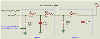
For 52820-QDAA, what load impedance is preferred seen into the matching network?   I mean the total load impedance of C3, L1, C4, L2, RF trace and antenna.

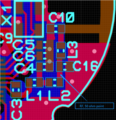
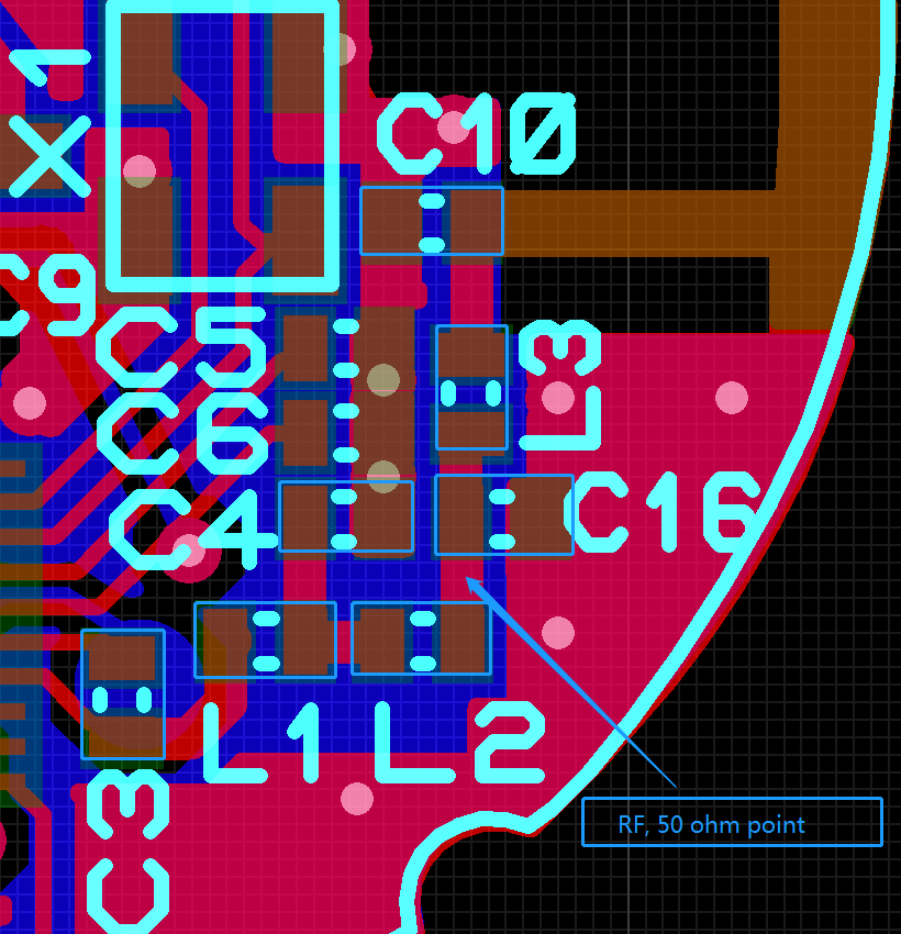
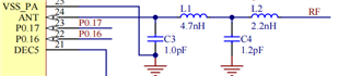
Since our product is small and layout can not be exactly same as recommended, we have to change C1, L1, C4, L2 values if needed, then measure impedance at ANT PIN to make sure to be preferred by 52820-QDAA. So we need to know the load impedance seen into the matching network

Here is another post which is talking about NRF52833-QIAA , a similar question.  Can anybody help me out? Thanks!

https://devzone.nordicsemi.com/f/nordic-q-a/84014/what-is-the-output-impedance-of-the-ant1-antenna-pin-on-the-nrf52833-qiaa/349797#349797

Best regards,

Bob

搜索

复制

Parents
  • The matching networks for the nRF52833 QIAA and nRF52830 QDAA are identical so the same applies for the nRF52820 as well. You should see 35 -j46 ohm into the matching network from the ANT pin.

    But this will only tell you how to match it for the best output power and sensitivity. It doesn't say anything about attenuation of the harmonics. So pay attention to that as well. This is especially important when you transmit with 8 dBm.

Reply
  • The matching networks for the nRF52833 QIAA and nRF52830 QDAA are identical so the same applies for the nRF52820 as well. You should see 35 -j46 ohm into the matching network from the ANT pin.

    But this will only tell you how to match it for the best output power and sensitivity. It doesn't say anything about attenuation of the harmonics. So pay attention to that as well. This is especially important when you transmit with 8 dBm.

Children
  • Hi ketiljo, thank you very much for quick answer!

    I will get back to you later.

  • Hi, I am coming back, See my design:

    top copper

    bottom copper

    My questions are:

    (1) Remove chip, measure S11 at ANT-PIN, is it right?

    (2) When I am adjusting network 1 for 35 -j46 impedance, I must break the line at RF point (50 ohm point) ?  If so, what should I connect at the right pad of L2? 

    (3) If I do not break line at RF point, keep network 1 using recommended component values, that mean I am measuring the total impedance of Network 1, Network 2 and Antenna. Can I only change network 2 component values to make product working well?  The antenna is simulated in HFSS software already. See simulate result:

    If yes, what value should be the total impedance ?

    Best regards,

    Bob

  • Your layout is close enough to the reference layout so I suggest you measure this differently. Setup the radio in constant carrier TX mode and the output power you are going to use. Measure S22 of the matching network (after L2, seen into the radio) and match for 50 - 70 ohm. Measure output power and harmonics at the same place. 

    1) Yes

    2) 50 ohm load (resistor) from L2 to ground

    3)

    If the circuitry after L2 gave a 50 ohm impedance, then you should see when you measure the total impedance seen from C3. But again, it's easier to measure S22 with the radio operating. 

  • Hi ketiljo,  I am measuring S22 at RF point, removed Network 2 components, but didn't break line at RF point. Did NOT setup the radio in constant carrier TX mode, the chip is idle. The result is far away from expected 50 ohm.

    S22 result - smith:

    S22 result - Return loss:

    Questions:

    (1) S22 result is very far from 50 ohm , is my measure method wrong? 

    (2) If I setup the radio in constant carrier TX mode, S22 result will be same as above, right?

    (3) I did not break line at RF point, does it effect result much ? 

    Best regards,

    Bob

  • You need to break the connection between L2 and C16 to get a correct reading. And you need to set the radio in TX mode, there's a great difference there. 

    Ans make sure the cable's outer conductor is soldered to the ground plane. Have you calibrated the cable?

Related