Hello,
NCS1.9.1, nRF5340DK+nRF21540EK, Windows10 X64, VS Code,
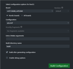
not find [nRF21540EK_nRF5340],
about software: how to create project build?
are there any samples?
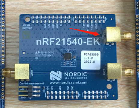
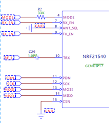
about hardware: where is TXR connected? what is its function?
thanks
Best Regards
Hi,
about software: how to create project build?
See http://developer.nordicsemi.com/nRF_Connect_SDK/doc/latest/nrf/ug_radio_fem.html#programming
where is TXR connected? what is its function?
It's for radio input. Since the nrf21540 is more or less just a power amplifier with the option to select between two antennas and adjust the power output. So the TRX pin is the radio in, so if we are to use the nrf52840 as an example it will be ANT pin on 52840 -> TRX on 21540
See https://infocenter.nordicsemi.com/topic/ps_nrf21540/chapters/hw_layout/pin/doc/frontpage.html?cp=7_0_0_8_0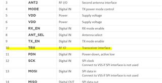
Regards,
Amanda
Hello,
thank you very much,
I follow the link.
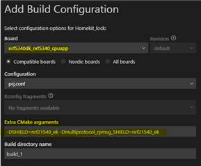
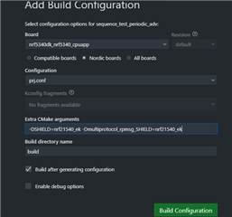
Extra CMake arguments:
-DSHIELD=nrf21540_ek -Dmultiprotocol_rpmsg_SHIELD=nrf21540_ek
but i'm failed, and the link not say how to change tx_power/selet ant/enable tx_en by sources code.
can you fix the project?
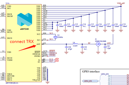
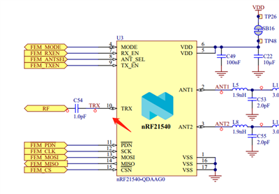
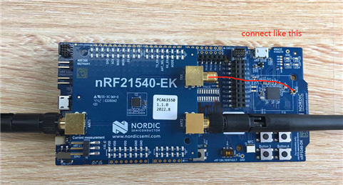
TRX connect like this?
Best Regards

Hi,
yoyou said:can you fix the project?
Please install NCS under C:\ and try again.
yoyou said:the link not say how to change tx_power/selet ant/enable tx_en by sources code.
You can refer to https://github.com/nrfconnect/sdk-zephyr/tree/main/samples/bluetooth/hci_pwr_ctrl
yoyou said:TRX connect like this?
Yes.
-Amanda
Hi,
thanks for reply,
i've install NCS1.9.1 under C:\
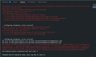
but still got error.
the file hci_rpmsg.overlay write error.
the code rar
other question:
1.
set_tx_power(BT_HCI_VS_LL_HANDLE_TYPE_ADV, 0, TRANSMIT_POWER_dBm);
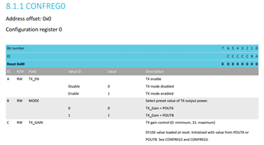
TRANSMIT_POWER_dBm undefine, is it value 0-31? max power is 31.
2.
how to select ant? unable to understand file of nrF21540_PS_v1.2.pdf.
is it set pin ANT_SEL logic level high will select ant2?
3.
RX_EN and TX_EN,
set pin logic level high will be enable?
Best Regards
Hi,Amanda
see:
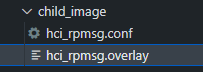
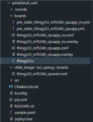
child_image\hci_rpmsg.conf
child_image\hci_rpmsg.overlay
From the above description,
does that mean the following?
Hardware:
Software:
thanks
Best Regards
Hi,
yoyou said:child_image\hci_rpmsg.overlay
That means the nRF21540 GPIO mode implementation of FEM is compatible with this device and implements the 3-pin PA/LNA interface. See GPIO mode. To use the SPI interface, see SPI/GPIO mode.
yoyou said:Only use ANT1;
There is an optional property to select antenna:
ant-sel-gpios - GPIO characteristic of the device that controls the ANT_SEL signal of devices that support antenna diversity
yoyou said:TX power set to maximum 20dBm (Fixed value);
CONFIG_BT_CTLR_TX_PWR_MINUS_20=y is set to -20 dBm.
Currently, we don't support run-time switching of TX gain by the application. It needs to be configured in Kconfig, passed to the child image just the way you did it with child_image/hci_rpmsg.conf and it is set by the network core on initialization. The relevant piece of code: https://github.com/nrfconnect/sdk-nrf/blob/v1.9.1/subsys/mpsl/fem/mpsl_fem.c#L284-L295
The code I provided is for nrf21540dk_nrf52840, and it cannot apply to nRF5340DK+nRF21540EK. So I would remove them.
-Amanda
Hi,
yoyou said:child_image\hci_rpmsg.overlay
That means the nRF21540 GPIO mode implementation of FEM is compatible with this device and implements the 3-pin PA/LNA interface. See GPIO mode. To use the SPI interface, see SPI/GPIO mode.
yoyou said:Only use ANT1;
There is an optional property to select antenna:
ant-sel-gpios - GPIO characteristic of the device that controls the ANT_SEL signal of devices that support antenna diversity
yoyou said:TX power set to maximum 20dBm (Fixed value);
CONFIG_BT_CTLR_TX_PWR_MINUS_20=y is set to -20 dBm.
Currently, we don't support run-time switching of TX gain by the application. It needs to be configured in Kconfig, passed to the child image just the way you did it with child_image/hci_rpmsg.conf and it is set by the network core on initialization. The relevant piece of code: https://github.com/nrfconnect/sdk-nrf/blob/v1.9.1/subsys/mpsl/fem/mpsl_fem.c#L284-L295
The code I provided is for nrf21540dk_nrf52840, and it cannot apply to nRF5340DK+nRF21540EK. So I would remove them.
-Amanda
Hi,Amanda
thank you very much,
To put it another way.
child_image\hci_rpmsg.overlay
above, i want only use ANT1 fixed,and not use SPI control (3 pin mode).
is the SCH(ANT_SEL---GND) and overlay configuration correct?
child_image\hci_rpmsg.conf
above, i want to:
is the configuration correct?
thanks
Best Regards
Hi,
For hardware connecting, see You can refer to our reference design Schematic with single antenna.
yoyou said:is the SCH(ANT_SEL---GND) and overlay configuration correct?
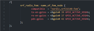
It might need to change name_of_fem_node to nrf21540_fem, so it would look like
/ {
      nrf_radio_fem: nrf21540_fem {
         compatible  = "nordic,nrf21540-fem";
         tx-en-gpios = <&gpio0 13 GPIO_ACTIVE_HIGH>;
         rx-en-gpios = <&gpio0 14 GPIO_ACTIVE_HIGH>;
         pdn-gpios   = <&gpio0 15 GPIO_ACTIVE_HIGH>;
   };
};
yoyou said:is the configuration correct?
The `CONFIG_MPSL_FEM_*` configuration looks fine, but because the BT_CTLR_TX_PWR_ is not being used by the SDC in the code, to set TX power for Bluetooth, you need to use HCI commands. This is a known issue, see Known issues — nRF Connect SDK 1.9.99 documentation (nordicsemi.com). If you could use nRF21540DK, here is an example in this thread. That might be easier.
-Amanda
Hi,
thanks for reply
thread. adv_nRF21540_20dBm.zip
not for nRF5340DK+nRF21540EK,
in devzone,i've search about it, perhaps many people are looking for this problem, so the authorities need to make a valid sample for nRF5340DK+nRF21540EK.
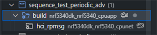
rar is my test project test_periodic_adv ,
i want to set max power and max GAIN for adv, (all maximum)
it is also desirable to enable SPI controls,but i write overlay file wrong.
If possible, please fixed conf and overlay file and upload a complete project,
it can be used as an official example for many people.
thanks
Best Regards
Hi,
The team said setting SHIELD variable does that part for the overlay and config. There's no need to set any additional Kconfig options manually. If you're building a BLE-only application (without 802.15.4) then the child image chosen for the network core is going to be hci_rpmsg, so the SHIELD variable should actually be set for that child image:
west build -b nrf5340dk_nrf5340_cpuapp -- -DSHIELD=nrf21540_ek -Dhci_rpmsg_SHIELD=nrf21540_ek
The bluetooth would get the FEM TX power. So all standard Bluetooth samples should work as long as you take the sample and enable the EK overlay (-DSHIELD=nrf21540_ek). It doen't need extra setting in the BLE application.
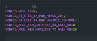
I use the hci_rpmsg.conf with BLE sample without modification of code
# FEM
CONFIG_MPSL_FEM=y
CONFIG_MPSL_FEM_NRF21540_RX_GAIN_DB=0
CONFIG_MPSL_FEM_NRF21540_TX_GAIN_DB=20
CONFIG_BT_CTLR_TX_PWR_DYNAMIC_CONTROL=y
I get the reslut in the Lab:
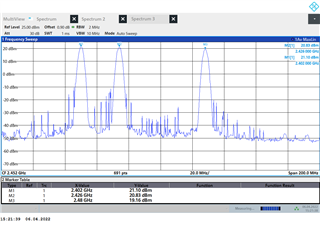
-Amanda
HI,
thanks for reply,
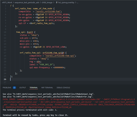
i follow Working with RF front-end modules — nRF Connect SDK 1.9.99 documentation (nordicsemi.com)
/{
        nrf_radio_fem: nrf21540_fem {
                compatible  = "nordic,nrf21540-fem";
                tx-en-gpios = <&gpio0 39 GPIO_ACTIVE_HIGH>;	//P1.07
                rx-en-gpios = <&gpio0 37 GPIO_ACTIVE_LOW>;	//P1.05
                pdn-gpios   = <&gpio0 42 GPIO_ACTIVE_HIGH>;	//P1.11
                spi-if = <&nrf_radio_fem_spi>;
        };

        fem_spi: &spi3 {
                status = "okay";
                sck-pin = <47>;	//P1.15
                miso-pin = <46>;//P1.14
                mosi-pin = <45>;//P1.13
                cs-gpios = <&gpio0 44 GPIO_ACTIVE_LOW>;//P1.12

                nrf_radio_fem_spi: nrf21540_fem_spi@0 {
                        compatible = "nordic,nrf21540-fem-spi";
                        status = "okay";
                        reg = <0>;
                        label = "FEM_SPI_IF";
                        spi-max-frequency = <8000000>;
                };
	};
};
the overlay error,
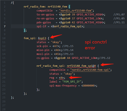
Best Regards