nrf5340 and BMI270 issue

Hello, I'm having the same issue as in this thread but the proposed solutions doesn't work for me. This is the output from the terminal:

*** Booting Zephyr OS build v2.7.99-ncs1-1 ***
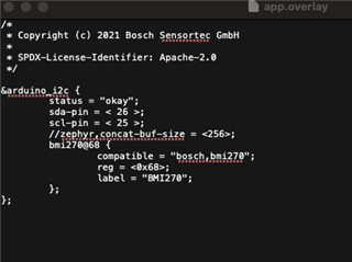
Could not get BMI270 device

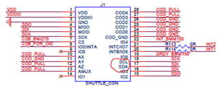
I tried using SPI earlier but that didn't work either.

I am on mac and using vscode to build and flash.

Parents
  • Hi,


    Which pins are you using for I2C (or SPI) ? How does your overlay file look like?


    Kind regards,

    Håkon

  • Hello. I used the bmi 270 example provided by zephyr https://github.com/zephyrproject-rtos/zephyr/tree/main/samples/sensor/bmi270

    With overlay file modified as such to use pins 25 and 26 for scl/sda:

    I attached them to these pins on the breakout board:

    Zephyr.dts looks like the following:

    /dts-v1/;
    
    / {
    	#address-cells = < 0x1 >;
    	#size-cells = < 0x1 >;
    	model = "Nordic NRF5340 DK NRF5340 Application";
    	compatible = "nordic,nrf5340-dk-nrf5340-cpuapp";
    	chosen {
    		zephyr,entropy = &cryptocell;
    		zephyr,flash-controller = &flash_controller;
    		zephyr,console = &uart0;
    		zephyr,shell-uart = &uart0;
    		zephyr,uart-mcumgr = &uart0;
    		zephyr,bt-mon-uart = &uart0;
    		zephyr,bt-c2h-uart = &uart0;
    		zephyr,ipc_shm = &sram0_shared;
    		zephyr,sram = &sram0_image;
    		zephyr,flash = &flash0;
    		zephyr,code-partition = &slot0_partition;
    		zephyr,sram-secure-partition = &sram0_s;
    		zephyr,sram-non-secure-partition = &sram0_ns;
    	};
    	aliases {
    		led0 = &led0;
    		led1 = &led1;
    		led2 = &led2;
    		led3 = &led3;
    		pwm-led0 = &pwm_led0;
    		sw0 = &button0;
    		sw1 = &button1;
    		sw2 = &button2;
    		sw3 = &button3;
    		bootloader-led0 = &led0;
    	};
    	soc {
    		#address-cells = < 0x1 >;
    		#size-cells = < 0x1 >;
    		compatible = "nordic,nRF5340-CPUAPP-QKAA", "nordic,nRF5340-CPUAPP", "nordic,nRF53", "simple-bus";
    		interrupt-parent = < &nvic >;
    		ranges;
    		nvic: interrupt-controller@e000e100 {
    			#address-cells = < 0x1 >;
    			compatible = "arm,v8m-nvic";
    			reg = < 0xe000e100 0xc00 >;
    			interrupt-controller;
    			#interrupt-cells = < 0x2 >;
    			arm,num-irq-priority-bits = < 0x3 >;
    			phandle = < 0x1 >;
    		};
    		systick: timer@e000e010 {
    			compatible = "arm,armv8m-systick";
    			reg = < 0xe000e010 0x10 >;
    			status = "disabled";
    		};
    		ficr: ficr@ff0000 {
    			compatible = "nordic,nrf-ficr";
    			reg = < 0xff0000 0x1000 >;
    			status = "okay";
    		};
    		uicr: uicr@ff8000 {
    			compatible = "nordic,nrf-uicr";
    			reg = < 0xff8000 0x1000 >;
    			status = "okay";
    		};
    		sram0: memory@20000000 {
    			compatible = "mmio-sram";
    			reg = < 0x20000000 0x80000 >;
    		};
    		peripheral@50000000 {
    			#address-cells = < 0x1 >;
    			#size-cells = < 0x1 >;
    			ranges = < 0x0 0x50000000 0x10000000 >;
    			regulators: regulator@4000 {
    				compatible = "nordic,nrf-regulators";
    				reg = < 0x4000 0x1000 >;
    				status = "okay";
    			};
    			clock: clock@5000 {
    				compatible = "nordic,nrf-clock";
    				reg = < 0x5000 0x1000 >;
    				interrupts = < 0x5 0x1 >;
    				status = "okay";
    				label = "CLOCK";
    			};
    			power: power@5000 {
    				compatible = "nordic,nrf-power";
    				reg = < 0x5000 0x1000 >;
    				interrupts = < 0x5 0x1 >;
    				status = "okay";
    			};
    			i2c0: i2c@8000 {
    				compatible = "nordic,nrf-twim";
    				#address-cells = < 0x1 >;
    				#size-cells = < 0x0 >;
    				reg = < 0x8000 0x1000 >;
    				clock-frequency = < 0x186a0 >;
    				interrupts = < 0x8 0x1 >;
    				status = "disabled";
    				label = "I2C_0";
    			};
    			spi0: spi@8000 {
    				compatible = "nordic,nrf-spim";
    				#address-cells = < 0x1 >;
    				#size-cells = < 0x0 >;
    				reg = < 0x8000 0x1000 >;
    				interrupts = < 0x8 0x1 >;
    				status = "disabled";
    				label = "SPI_0";
    			};
    			uart0: uart@8000 {
    				compatible = "nordic,nrf-uarte";
    				reg = < 0x8000 0x1000 >;
    				interrupts = < 0x8 0x1 >;
    				status = "okay";
    				label = "UART_0";
    				current-speed = < 0x1c200 >;
    				tx-pin = < 0x14 >;
    				rx-pin = < 0x16 >;
    				rx-pull-up;
    				rts-pin = < 0x13 >;
    				cts-pin = < 0x15 >;
    				cts-pull-up;
    			};
    			i2c1: arduino_i2c: i2c@9000 {
    				compatible = "nordic,nrf-twim";
    				#address-cells = < 0x1 >;
    				#size-cells = < 0x0 >;
    				reg = < 0x9000 0x1000 >;
    				clock-frequency = < 0x186a0 >;
    				interrupts = < 0x9 0x1 >;
    				status = "okay";
    				label = "I2C_1";
    				sda-pin = < 0x1a >;
    				scl-pin = < 0x19 >;
    				bmi270@68 {
    					compatible = "bosch,bmi270";
    					reg = < 0x68 >;
    					label = "BMI270";
    				};
    			};
    			spi1: spi@9000 {
    				compatible = "nordic,nrf-spim";
    				#address-cells = < 0x1 >;
    				#size-cells = < 0x0 >;
    				reg = < 0x9000 0x1000 >;
    				interrupts = < 0x9 0x1 >;
    				status = "disabled";
    				label = "SPI_1";
    			};
    			uart1: arduino_serial: uart@9000 {
    				compatible = "nordic,nrf-uarte";
    				reg = < 0x9000 0x1000 >;
    				interrupts = < 0x9 0x1 >;
    				status = "disabled";
    				label = "UART_1";
    				current-speed = < 0x1c200 >;
    				tx-pin = < 0x21 >;
    				rx-pin = < 0x20 >;
    				rx-pull-up;
    			};
    			spi4: arduino_spi: spi@a000 {
    				compatible = "nordic,nrf-spim";
    				#address-cells = < 0x1 >;
    				#size-cells = < 0x0 >;
    				reg = < 0xa000 0x1000 >;
    				interrupts = < 0xa 0x1 >;
    				status = "disabled";
    				label = "SPI_4";
    				sck-pin = < 0x2f >;
    				miso-pin = < 0x2e >;
    				mosi-pin = < 0x2d >;
    				cs-gpios = < &arduino_header 0x10 0x1 >;
    			};
    			i2c2: i2c@b000 {
    				compatible = "nordic,nrf-twim";
    				#address-cells = < 0x1 >;
    				#size-cells = < 0x0 >;
    				reg = < 0xb000 0x1000 >;
    				clock-frequency = < 0x186a0 >;
    				interrupts = < 0xb 0x1 >;
    				status = "okay";
    				label = "I2C_2";
    				sda-pin = < 0x1a >;
    				scl-pin = < 0x19 >;
    			};
    			spi2: spi@b000 {
    				compatible = "nordic,nrf-spim";
    				#address-cells = < 0x1 >;
    				#size-cells = < 0x0 >;
    				reg = < 0xb000 0x1000 >;
    				interrupts = < 0xb 0x1 >;
    				status = "disabled";
    				label = "SPI_2";
    				sck-pin = < 0x1e >;
    				miso-pin = < 0x1d >;
    				mosi-pin = < 0x1f >;
    			};
    			uart2: uart@b000 {
    				compatible = "nordic,nrf-uarte";
    				reg = < 0xb000 0x1000 >;
    				interrupts = < 0xb 0x1 >;
    				status = "disabled";
    				label = "UART_2";
    			};
    			i2c3: i2c@c000 {
    				compatible = "nordic,nrf-twim";
    				#address-cells = < 0x1 >;
    				#size-cells = < 0x0 >;
    				reg = < 0xc000 0x1000 >;
    				clock-frequency = < 0x186a0 >;
    				interrupts = < 0xc 0x1 >;
    				status = "disabled";
    				label = "I2C_3";
    			};
    			spi3: spi@c000 {
    				compatible = "nordic,nrf-spim";
    				#address-cells = < 0x1 >;
    				#size-cells = < 0x0 >;
    				reg = < 0xc000 0x1000 >;
    				interrupts = < 0xc 0x1 >;
    				status = "disabled";
    				label = "SPI_3";
    			};
    			uart3: uart@c000 {
    				compatible = "nordic,nrf-uarte";
    				reg = < 0xc000 0x1000 >;
    				interrupts = < 0xc 0x1 >;
    				status = "disabled";
    				label = "UART_3";
    			};
    			adc: adc@e000 {
    				compatible = "nordic,nrf-saadc";
    				reg = < 0xe000 0x1000 >;
    				interrupts = < 0xe 0x1 >;
    				status = "okay";
    				label = "ADC_0";
    				#io-channel-cells = < 0x1 >;
    				phandle = < 0x6 >;
    			};
    			timer0: timer@f000 {
    				compatible = "nordic,nrf-timer";
    				status = "okay";
    				reg = < 0xf000 0x1000 >;
    				cc-num = < 0x6 >;
    				interrupts = < 0xf 0x1 >;
    				prescaler = < 0x0 >;
    				label = "TIMER_0";
    			};
    			timer1: timer@10000 {
    				compatible = "nordic,nrf-timer";
    				status = "okay";
    				reg = < 0x10000 0x1000 >;
    				cc-num = < 0x6 >;
    				interrupts = < 0x10 0x1 >;
    				prescaler = < 0x0 >;
    				label = "TIMER_1";
    			};
    			timer2: timer@11000 {
    				compatible = "nordic,nrf-timer";
    				status = "okay";
    				reg = < 0x11000 0x1000 >;
    				cc-num = < 0x6 >;
    				interrupts = < 0x11 0x1 >;
    				prescaler = < 0x0 >;
    				label = "TIMER_2";
    			};
    			rtc0: rtc@14000 {
    				compatible = "nordic,nrf-rtc";
    				reg = < 0x14000 0x1000 >;
    				cc-num = < 0x4 >;
    				interrupts = < 0x14 0x1 >;
    				status = "okay";
    				clock-frequency = < 0x8000 >;
    				prescaler = < 0x1 >;
    				label = "RTC_0";
    			};
    			rtc1: rtc@15000 {
    				compatible = "nordic,nrf-rtc";
    				reg = < 0x15000 0x1000 >;
    				cc-num = < 0x4 >;
    				interrupts = < 0x15 0x1 >;
    				status = "okay";
    				clock-frequency = < 0x8000 >;
    				prescaler = < 0x1 >;
    				label = "RTC_1";
    			};
    			dppic: dppic@17000 {
    				compatible = "nordic,nrf-dppic";
    				reg = < 0x17000 0x1000 >;
    				status = "okay";
    				label = "DPPIC";
    			};
    			wdt: wdt0: watchdog@18000 {
    				compatible = "nordic,nrf-watchdog";
    				reg = < 0x18000 0x1000 >;
    				interrupts = < 0x18 0x1 >;
    				status = "okay";
    				label = "WDT";
    			};
    			wdt1: watchdog@19000 {
    				compatible = "nordic,nrf-watchdog";
    				reg = < 0x19000 0x1000 >;
    				interrupts = < 0x19 0x1 >;
    				status = "disabled";
    				label = "WDT_1";
    			};
    			egu0: egu@1b000 {
    				compatible = "nordic,nrf-egu";
    				reg = < 0x1b000 0x1000 >;
    				interrupts = < 0x1b 0x1 >;
    				status = "okay";
    			};
    			egu1: egu@1c000 {
    				compatible = "nordic,nrf-egu";
    				reg = < 0x1c000 0x1000 >;
    				interrupts = < 0x1c 0x1 >;
    				status = "okay";
    			};
    			egu2: egu@1d000 {
    				compatible = "nordic,nrf-egu";
    				reg = < 0x1d000 0x1000 >;
    				interrupts = < 0x1d 0x1 >;
    				status = "okay";
    			};
    			egu3: egu@1e000 {
    				compatible = "nordic,nrf-egu";
    				reg = < 0x1e000 0x1000 >;
    				interrupts = < 0x1e 0x1 >;
    				status = "okay";
    			};
    			egu4: egu@1f000 {
    				compatible = "nordic,nrf-egu";
    				reg = < 0x1f000 0x1000 >;
    				interrupts = < 0x1f 0x1 >;
    				status = "okay";
    			};
    			egu5: egu@20000 {
    				compatible = "nordic,nrf-egu";
    				reg = < 0x20000 0x1000 >;
    				interrupts = < 0x20 0x1 >;
    				status = "okay";
    			};
    			pwm0: pwm@21000 {
    				compatible = "nordic,nrf-pwm";
    				reg = < 0x21000 0x1000 >;
    				interrupts = < 0x21 0x1 >;
    				status = "okay";
    				label = "PWM_0";
    				#pwm-cells = < 0x1 >;
    				ch0-pin = < 0x1c >;
    				phandle = < 0x4 >;
    			};
    			pwm1: pwm@22000 {
    				compatible = "nordic,nrf-pwm";
    				reg = < 0x22000 0x1000 >;
    				interrupts = < 0x22 0x1 >;
    				status = "disabled";
    				label = "PWM_1";
    				#pwm-cells = < 0x1 >;
    			};
    			pwm2: pwm@23000 {
    				compatible = "nordic,nrf-pwm";
    				reg = < 0x23000 0x1000 >;
    				interrupts = < 0x23 0x1 >;
    				status = "disabled";
    				label = "PWM_2";
    				#pwm-cells = < 0x1 >;
    			};
    			pwm3: pwm@24000 {
    				compatible = "nordic,nrf-pwm";
    				reg = < 0x24000 0x1000 >;
    				interrupts = < 0x24 0x1 >;
    				status = "disabled";
    				label = "PWM_3";
    				#pwm-cells = < 0x1 >;
    			};
    			pdm0: pdm@26000 {
    				compatible = "nordic,nrf-pdm";
    				reg = < 0x26000 0x1000 >;
    				interrupts = < 0x26 0x1 >;
    				status = "disabled";
    				label = "PDM_0";
    			};
    			i2s0: i2s@28000 {
    				compatible = "nordic,nrf-i2s";
    				#address-cells = < 0x1 >;
    				#size-cells = < 0x0 >;
    				reg = < 0x28000 0x1000 >;
    				interrupts = < 0x28 0x1 >;
    				status = "disabled";
    				label = "I2S_0";
    			};
    			ipc: ipc@2a000 {
    				compatible = "nordic,nrf-ipc";
    				reg = < 0x2a000 0x1000 >;
    				interrupts = < 0x2a 0x1 >;
    				status = "okay";
    				label = "IPC";
    			};
    			qspi: qspi@2b000 {
    				compatible = "nordic,nrf-qspi";
    				#address-cells = < 0x1 >;
    				#size-cells = < 0x0 >;
    				reg = < 0x2b000 0x1000 >, < 0x10000000 0x10000000 >;
    				reg-names = "qspi", "qspi_mm";
    				interrupts = < 0x2b 0x1 >;
    				status = "okay";
    				label = "QSPI";
    				sck-pin = < 0x11 >;
    				io-pins = < 0xd >, < 0xe >, < 0xf >, < 0x10 >;
    				csn-pins = < 0x12 >;
    				mx25r64: mx25r6435f@0 {
    					compatible = "nordic,qspi-nor";
    					reg = < 0x0 >;
    					writeoc = "pp4io";
    					readoc = "read4io";
    					sck-frequency = < 0x7a1200 >;
    					label = "MX25R64";
    					jedec-id = [ C2 28 17 ];
    					sfdp-bfp = [ E5 20 F1 FF FF FF FF 03 44 EB 08 6B 08 3B 04 BB EE FF FF FF FF FF 00 FF FF FF 00 FF 0C 20 0F 52 10 D8 00 FF 23 72 F5 00 82 ED 04 CC 44 83 68 44 30 B0 30 B0 F7 C4 D5 5C 00 BE 29 FF F0 D0 FF FF ];
    					size = < 0x4000000 >;
    					has-dpd;
    					t-enter-dpd = < 0x2710 >;
    					t-exit-dpd = < 0x88b8 >;
    				};
    			};
    			qdec0: qdec@33000 {
    				compatible = "nordic,nrf-qdec";
    				reg = < 0x33000 0x1000 >;
    				interrupts = < 0x33 0x1 >;
    				status = "disabled";
    				label = "QDEC_0";
    			};
    			qdec1: qdec@34000 {
    				compatible = "nordic,nrf-qdec";
    				reg = < 0x34000 0x1000 >;
    				interrupts = < 0x34 0x1 >;
    				status = "disabled";
    				label = "QDEC_1";
    			};
    			usbd: zephyr_udc0: usbd@36000 {
    				compatible = "nordic,nrf-usbd";
    				reg = < 0x36000 0x1000 >;
    				interrupts = < 0x36 0x1 >;
    				num-bidir-endpoints = < 0x1 >;
    				num-in-endpoints = < 0x7 >;
    				num-out-endpoints = < 0x7 >;
    				num-isoin-endpoints = < 0x1 >;
    				num-isoout-endpoints = < 0x1 >;
    				status = "okay";
    				label = "USBD";
    			};
    			flash_controller: flash-controller@39000 {
    				compatible = "nordic,nrf53-flash-controller";
    				reg = < 0x39000 0x1000 >;
    				#address-cells = < 0x1 >;
    				#size-cells = < 0x1 >;
    				label = "NRF_FLASH_DRV_NAME";
    				flash0: flash@0 {
    					compatible = "soc-nv-flash";
    					label = "NRF_FLASH";
    					erase-block-size = < 0x1000 >;
    					write-block-size = < 0x4 >;
    					reg = < 0x0 0x100000 >;
    					partitions {
    						compatible = "fixed-partitions";
    						#address-cells = < 0x1 >;
    						#size-cells = < 0x1 >;
    						boot_partition: partition@0 {
    							label = "mcuboot";
    							reg = < 0x0 0x10000 >;
    						};
    						slot0_partition: partition@10000 {
    							label = "image-0";
    							reg = < 0x10000 0x40000 >;
    						};
    						slot0_ns_partition: partition@50000 {
    							label = "image-0-nonsecure";
    							reg = < 0x50000 0x30000 >;
    						};
    						slot1_partition: partition@80000 {
    							label = "image-1";
    							reg = < 0x80000 0x40000 >;
    						};
    						slot1_ns_partition: partition@c0000 {
    							label = "image-1-nonsecure";
    							reg = < 0xc0000 0x30000 >;
    						};
    						scratch_partition: partition@f0000 {
    							label = "image-scratch";
    							reg = < 0xf0000 0xa000 >;
    						};
    						storage_partition: partition@fa000 {
    							label = "storage";
    							reg = < 0xfa000 0x6000 >;
    						};
    					};
    				};
    			};
    			kmu: kmu@39000 {
    				compatible = "nordic,nrf-kmu";
    				reg = < 0x39000 0x1000 >;
    				interrupts = < 0x39 0x1 >;
    				status = "okay";
    			};
    			vmc: vmc@81000 {
    				compatible = "nordic,nrf-vmc";
    				reg = < 0x81000 0x1000 >;
    				status = "okay";
    			};
    			gpio0: gpio@842500 {
    				compatible = "nordic,nrf-gpio";
    				gpio-controller;
    				reg = < 0x842500 0x300 >;
    				#gpio-cells = < 0x2 >;
    				label = "GPIO_0";
    				status = "okay";
    				port = < 0x0 >;
    				phandle = < 0x3 >;
    			};
    			gpio1: gpio@842800 {
    				compatible = "nordic,nrf-gpio";
    				gpio-controller;
    				reg = < 0x842800 0x300 >;
    				#gpio-cells = < 0x2 >;
    				ngpios = < 0x10 >;
    				label = "GPIO_1";
    				status = "okay";
    				port = < 0x1 >;
    				phandle = < 0x5 >;
    			};
    		};
    		spu: spu@50003000 {
    			compatible = "nordic,nrf-spu";
    			reg = < 0x50003000 0x1000 >;
    			interrupts = < 0x3 0x1 >;
    			status = "okay";
    		};
    		gpiote: gpiote0: gpiote@5000d000 {
    			compatible = "nordic,nrf-gpiote";
    			reg = < 0x5000d000 0x1000 >;
    			interrupts = < 0xd 0x5 >;
    			status = "okay";
    			label = "GPIOTE_0";
    		};
    		cryptocell: crypto@50844000 {
    			compatible = "nordic,nrf-cc312";
    			reg = < 0x50844000 0x1000 >;
    			label = "CRYPTOCELL";
    			status = "okay";
    			#address-cells = < 0x1 >;
    			#size-cells = < 0x1 >;
    			cryptocell312: crypto@50845000 {
    				compatible = "arm,cryptocell-312";
    				reg = < 0x50845000 0x1000 >;
    				interrupts = < 0x44 0x1 >;
    				label = "CRYPTOCELL312";
    			};
    		};
    		gpiote1: gpiote@4002f000 {
    			compatible = "nordic,nrf-gpiote";
    			reg = < 0x4002f000 0x1000 >;
    			interrupts = < 0x2f 0x5 >;
    			status = "disabled";
    			label = "GPIOTE_1";
    		};
    	};
    	pinctrl: pin-controller {
    		compatible = "nordic,nrf-pinctrl";
    	};
    	cpus {
    		#address-cells = < 0x1 >;
    		#size-cells = < 0x0 >;
    		cpu@0 {
    			device_type = "cpu";
    			compatible = "arm,cortex-m33f";
    			reg = < 0x0 >;
    			#address-cells = < 0x1 >;
    			#size-cells = < 0x1 >;
    			swo-ref-frequency = < 0x3d09000 >;
    			mpu: mpu@e000ed90 {
    				compatible = "arm,armv8m-mpu";
    				reg = < 0xe000ed90 0x40 >;
    				arm,num-mpu-regions = < 0x8 >;
    			};
    		};
    	};
    	leds {
    		compatible = "gpio-leds";
    		led0: led_0 {
    			gpios = < &gpio0 0x1c 0x1 >;
    			label = "Green LED 0";
    		};
    		led1: led_1 {
    			gpios = < &gpio0 0x1d 0x1 >;
    			label = "Green LED 1";
    		};
    		led2: led_2 {
    			gpios = < &gpio0 0x1e 0x1 >;
    			label = "Green LED 2";
    		};
    		led3: led_3 {
    			gpios = < &gpio0 0x1f 0x1 >;
    			label = "Green LED 3";
    		};
    	};
    	pwmleds {
    		compatible = "pwm-leds";
    		pwm_led0: pwm_led_0 {
    			pwms = < &pwm0 0x1c >;
    		};
    	};
    	buttons {
    		compatible = "gpio-keys";
    		button0: button_0 {
    			gpios = < &gpio0 0x17 0x11 >;
    			label = "Push button 1";
    		};
    		button1: button_1 {
    			gpios = < &gpio0 0x18 0x11 >;
    			label = "Push button 2";
    		};
    		button2: button_2 {
    			gpios = < &gpio0 0x8 0x11 >;
    			label = "Push button 3";
    		};
    		button3: button_3 {
    			gpios = < &gpio0 0x9 0x11 >;
    			label = "Push button 4";
    		};
    	};
    	arduino_header: connector {
    		compatible = "arduino-header-r3";
    		#gpio-cells = < 0x2 >;
    		gpio-map-mask = < 0xffffffff 0xffffffc0 >;
    		gpio-map-pass-thru = < 0x0 0x3f >;
    		gpio-map = < 0x0 0x0 &gpio0 0x4 0x0 >, < 0x1 0x0 &gpio0 0x5 0x0 >, < 0x2 0x0 &gpio0 0x6 0x0 >, < 0x3 0x0 &gpio0 0x7 0x0 >, < 0x4 0x0 &gpio0 0x19 0x0 >, < 0x5 0x0 &gpio0 0x1a 0x0 >, < 0x6 0x0 &gpio1 0x0 0x0 >, < 0x7 0x0 &gpio1 0x1 0x0 >, < 0x8 0x0 &gpio1 0x4 0x0 >, < 0x9 0x0 &gpio1 0x5 0x0 >, < 0xa 0x0 &gpio1 0x6 0x0 >, < 0xb 0x0 &gpio1 0x7 0x0 >, < 0xc 0x0 &gpio1 0x8 0x0 >, < 0xd 0x0 &gpio1 0x9 0x0 >, < 0xe 0x0 &gpio1 0xa 0x0 >, < 0xf 0x0 &gpio1 0xb 0x0 >, < 0x10 0x0 &gpio1 0xc 0x0 >, < 0x11 0x0 &gpio1 0xd 0x0 >, < 0x12 0x0 &gpio1 0xe 0x0 >, < 0x13 0x0 &gpio1 0xf 0x0 >, < 0x14 0x0 &gpio1 0x2 0x0 >, < 0x15 0x0 &gpio1 0x3 0x0 >;
    		phandle = < 0x2 >;
    	};
    	arduino_adc: analog-connector {
    		compatible = "arduino,uno-adc";
    		#io-channel-cells = < 0x1 >;
    		io-channel-map = < 0x0 &adc 0x0 >, < 0x1 &adc 0x1 >, < 0x2 &adc 0x2 >, < 0x3 &adc 0x3 >, < 0x4 &adc 0x4 >, < 0x5 &adc 0x5 >;
    	};
    	reserved-memory {
    		#address-cells = < 0x1 >;
    		#size-cells = < 0x1 >;
    		ranges;
    		sram0_image: image@20000000 {
    			reg = < 0x20000000 0x70000 >;
    		};
    		sram0_s: image_s@20000000 {
    			reg = < 0x20000000 0x40000 >;
    		};
    		sram0_ns: image_ns@20040000 {
    			reg = < 0x20040000 0x30000 >;
    		};
    		sram0_shared: memory@20070000 {
    			reg = < 0x20070000 0x10000 >;
    		};
    	};
    };
    

  • Hi,


    The overlay looks ok. Have you scoped SCL and SDA pins to see if there's any activity?

    Both pins shall be active low, ie. idling at VDD.


    Kind regards,

    Håkon

Reply Children
Related