Hi,
I'm gonna make my first attemp with the RF 2.4GHZ antenna, and want to get a good performace for the RF transmission meaning minimum loss of the power transmission and the maximum range as possible. I'm using the NRF51822-QFAA-R7 Bluetooth Smart with the Johanson Technology Balun the 2450BM14E0003T and the 2450AT43A100E as the antenna :
www.johansontechnology.com/.../2450BM14E0003.pdf
www.johansontechnology.com/.../2450AT43A100.pdf
The first thing i start by calculating the Line width to match the 50Ω characteristic impedance. its mandatory to know the PCB material, for that i'm gonna use the 2 PCB layer from OSHPARK. their characteristic for PCB are :
-
All 2 boards are FR4 170Tg/290Td
-
They’re 1.6mm thick (0.063 inches) with 1 ounce copper on both sides.
using the AppCad software i tried to calculate the trace width , the result are bellow :

the size are they correct ?
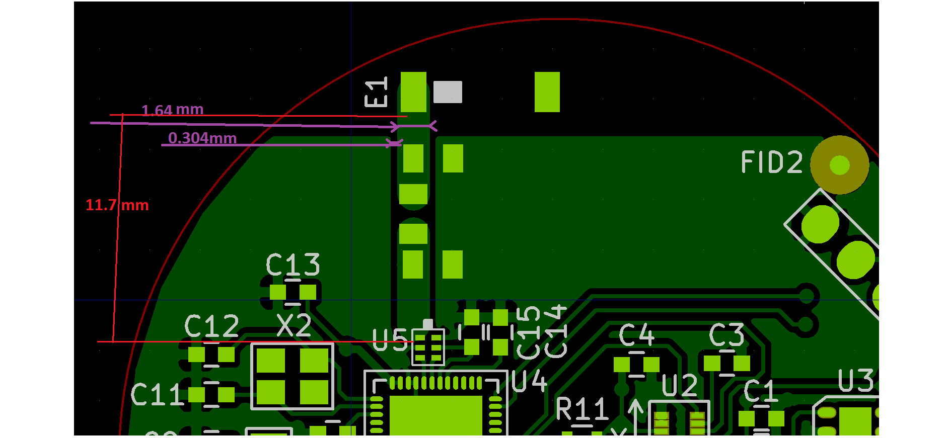
and this is how its looks like my PCB

i put also a PI network and i didn't know how can i guess approximately the value of the PI netwrok ?? or should i put a shunt resistor with 0 Ohm then use the Spectrum analyzer ? is there other solution than using Spectrum analyzer to tune the antenna ??
What do you think about the PCB ? can i have a chance to get a good RF transmission ?


