Read debugs from nrf52840 dongle on nrf52840 DK

Hi,

I've surfed through the forum for the lot of similar posts but couldn't get it to work yet. So, apologies if this seems repetitive.

My ultimate goal is to port the program that is running perfectly on nrf52840 DK to nrf52840 dongle. Before we get there, I'm currently trying to read debugs from the dongle on the DK for basic checking.

I've gone through this tutorial and included the voltage setter script in the programs. For more background, I'm trying to follow this tutorial

Problem

This is the code I've uploaded into the dongle. It's just the sample blinky code with voltage setter snippet and printk statement.  

/*
 * Copyright (c) 2016 Intel Corporation
 *
 * SPDX-License-Identifier: Apache-2.0
 */

#include <zephyr.h>
#include <device.h>
#include <devicetree.h>
#include <drivers/gpio.h>
#include <sys/printk.h>

/* 1000 msec = 1 sec */
#define SLEEP_TIME_MS   1000

/* The devicetree node identifier for the "led0" alias. */
#define LED0_NODE DT_ALIAS(led0)

#if DT_NODE_HAS_STATUS(LED0_NODE, okay)
#define LED0	DT_GPIO_LABEL(LED0_NODE, gpios)
#define PIN	DT_GPIO_PIN(LED0_NODE, gpios)
#define FLAGS	DT_GPIO_FLAGS(LED0_NODE, gpios)
#else
/* A build error here means your board isn't set up to blink an LED. */
#error "Unsupported board: led0 devicetree alias is not defined"
#define LED0	""
#define PIN	0
#define FLAGS	0
#endif

void main(void)
{
	/* Change voltage if we use nrf DK to program the dongle (code snippet from tutorial)*/
	if ((NRF_UICR->REGOUT0 & UICR_REGOUT0_VOUT_Msk) == (UICR_REGOUT0_VOUT_DEFAULT << UICR_REGOUT0_VOUT_Pos)){
		NRF_NVMC->CONFIG = NVMC_CONFIG_WEN_Wen;
		while (NRF_NVMC->READY == NVMC_READY_READY_Busy){}

		NRF_UICR->REGOUT0 = (NRF_UICR->REGOUT0 & ~((uint32_t)UICR_REGOUT0_VOUT_Msk)) |
							(UICR_REGOUT0_VOUT_3V0 << UICR_REGOUT0_VOUT_Pos);

		NRF_NVMC->CONFIG = NVMC_CONFIG_WEN_Ren;
		while (NRF_NVMC->READY == NVMC_READY_READY_Busy){}

		// System reset is needed to update UICR registers.
		NVIC_SystemReset();
	}
	/*******************************************/

	const struct device *dev;
	bool led_is_on = true;
	int ret;

	dev = device_get_binding(LED0);
	if (dev == NULL) {
		return;
	}

	ret = gpio_pin_configure(dev, PIN, GPIO_OUTPUT_ACTIVE | FLAGS);
	if (ret < 0) {
		return;
	}

	while (1) {
		gpio_pin_set(dev, PIN, (int)led_is_on);
		led_is_on = !led_is_on;
		printk("Hello World! %s\n", CONFIG_BOARD);
		k_msleep(SLEEP_TIME_MS);
	}
}

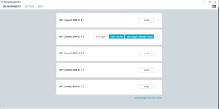
It's successfully built using the nRF connect for VS code extension and then directly uploading the .hex file using the "nRF connect for Desktop" programmer app. I can see the dongle blinking, so it works.

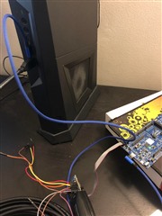
Now, I've connected the dongle and the DK via SWD interface and DEBUG OUT as seen in the picture. 

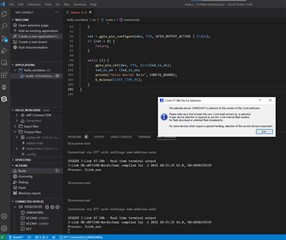
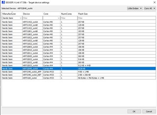
The dongle is still flashing the green LED but I cannot detect a serial port anymore. Instead, I can only see the two j-link virtual ports. None of them is printing any debug logs. There's also RTT logging feature on the VS code and when it's selected I get this pop up and choose the right board as shown. I can see the green LED on DK board flashing very fast although I have no idea why is that.

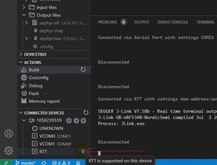
However, nothing is still printed.

My DK board is nRF52840_xxAA_Rev3(as seen on the programmer app). I can see the SB19 pad beside the DEBUG OUT header on the DK board but this post states it doesn't need to be soldered to use.

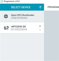
Also, I'm seeing both boards on the programmer which sounds wrong. 

I'm sure I'm missing something here but can't figure out what after debugging for over 6 hours, hence seeking help.

Thanks

  • Hi

    This seems like it should work, but I got a few ideas as to what could be going wrong. 

    First off, it might be that the RTT viewer in the nRF Terminal is not working as expected for some reason, but you could try out the J-Link RTT viewer instead, as that is a bit more stable. Also, can you show me how you've enabled the RTT logging in your application, and let me know what SDK and SDK version you're using for development?

    As for the green LED flashing "very fast", I assume you mean faster than expected when it runs the normal Blinky application, but can you still see it physically blinking or does it appear to just be on?

    Best regards,

    Simon

  • Hi, I'm using the nRF connect SDK v1.9.0 which is installed using the nRF Connect for Desktop toolchain manager app. 

    As for the RTT, I thought it was just a normal debug monitor. I havn't put in any code specific to that. I'd appreciate if you can give me an example snippet of what it should look like. Or is it possible to debug normally without RTT?

    The green LED flashing on the DK board seems constant now when I restarted. I didn't program anything on the DK board. Only the dongle is programmed with blinky. I believe green LED on DK board is turned on by default. 

    One more thing I noticed, the dongle gets into bootloader mode when the debugger(dk board) usb is plugged into PC. In order to run the blinky on the dongle, i have to unplug the dongle and plug it back in while debugger usb is still connected to PC. 

  • Hi again

    Okay, thank you for clarifying, I see I misunderstood multiple things here. It should still work as far as I can see, but yes, the nRF Connect SDK should be able to get an RTT output from a Dongle connected like this in VS code. Are you sure the debug pin header is soldered on the correct way on the bottom of the Dongle? Can you show me a picture of that as well?

    For the green LED I thought you said the led on the Dongle was blinking "really fast" so I thought something was wrong there, but I see now that this was likely LED5 on the DK, which indeed blinks to reflect activity on the debugger MCU.

    For the Dongle going into bootloader mode, does this happen even if the Dongle isn't connected with the debugger cable when the DK is plugged into the PC, or if the DK is OFF when you plug it in?

    I see you're using nRF Connect SDK v1.9.0. Is there a reason you're not using the latest version (v1.9.1) which has both features added and bugs/issues fixed?

    Best regards,

    Simon

  • Hi, I've adjust a few things from your feedback.

    1. I believe I soldered the pin header on dongle the opposite way. So, now I've reversed the connector cable as shown in the images. pic1pic2 However, I'm still not able to read the debugs. The manual says if DEBUG OUT is connected to the dongle, the DK board will operate from the donlge's nRF SOC instead of its own SOC. Could you tell me how I can check this? Does it mean we should only see one device in the nRF programmer app because now I'm see both DK and dongle boards.

    2. Yes it's the LED5 that's flashing

    3. After doing No. 1, the Dongle doesn't go into bootloader mode automatically anymore. (solved)

    4. I will update to v1.9.1, no problem. 

    Appreciate your help Slight smile

  • 1. From your latest pictures it looks like the pin header is soldered on correctly, but does your 10pin cable not have this "notch" in it? It should fit into the "slot" on the pin header, to ensure it is mounted correctly.

    If the Dongle is in Bootloader mode (pulsing red) it will still show up in the programmer app even when connected to the DK. And the DK will automatically choose the device connected to the debug out header if it's powered.

    Best regards,

    Simon

Related