Coap server not working on a third party module

Hi, 

I am building the CoAP client and sever example programs on a third party module (Reytac MDBT50Q). I am using Reytac dev board  MDBT50Q-DB-40. Unfortunately the example apps doesnt seem to work. I am using NRF Connect SDK 2.0.0. I tried the apps on Nordic nRF52840 Dev Kits and they work. I am using the same nrf52840dk_nrf52840.dts file with the Reytac module. 

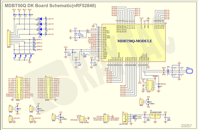
The Reytac dev board doesn't have the HFX oscillator on the dev board, probably it is available in the module itself. The dev board has a 32.7kHz crystal and is oscillating Vpp ~100mV. Dont know if this is too low. I couldnt find a spec for the LFXO in the datasheet.

When I look into the power supply on Dev board, I see VDDH tied to 3V3 and 10uH inductor between VDD and DCH. I reckon this means the power path would be 3V3->VDDH->REG0 DC/DC->REG1 (LDO or DC/DC)->System Power. I couldnt find the code section which handles the power control registers in coap client app. 

  1. Is 100mV LFXO acceptable?
  2. Where is power register configuration happens in coap client/server apps?

Thanks,

Parents
  • Hi,


    Is 100mV LFXO acceptable?

    This is usually enough. The real voltage is higher (probably > 200 mVpp), because when you're probing the pin, you're also loading it with the pin-probe.

    Where is power register configuration happens in coap client/server apps?

    CONFIG_BOARD_ENABLE_DCDC sets the DCDC, and here's the 32k clock control choices:

    https://developer.nordicsemi.com/nRF_Connect_SDK/doc/latest/kconfig/index.html#CONFIG_CLOCK_CONTROL_NRF_SOURCE


    I do not have experience with the dev board in question, but the module itself comes without an external LFCLK.

    If you have problems booting up, you can try to set this and see if that works:

    CONFIG_CLOCK_CONTROL_NRF_K32SRC_RC=y


    Kind regards,

    Håkon

  • Hey ,

    Thanks heaps for the info. 

    I will try CONFIG_BOARD_ENABLE_DCDC. How do you specify REG0 or REG1? 

    The modules dont come with internal LFCLK, but the dev board that they are mounted on has it. The module boots up and I can see the pairing LED blinking when I press pairing request button. Only issue is I cant make the client pair with it. The same client pairs with the server programmed to a nRF52840 DK. I assume this may be caused by the differences in hardware interfacing, but still cant figure out what. 

    This is the dev board schematic.

    Cheers,

  • I can see that the 

    CONFIG_BOARD_ENABLE_DCDC and

    CONFIG_BOARD_ENABLE_DCDC_HV are both set in Kconfig. So both REG0 and REG1 DC/DC must be  working. On the Reytac module, I see 1.8V on VDD, but on the nRF52840DK I see 3V0 for the same coap_server program, same DTS file. How is this possible?

    Funnily when I debug the program and check REGOUT0, it says 1.8V. So Raytac module is behaving right as far as VDD is concerned, but nRF52840 DK is not. What am I missing here?

    Is it possible to set the REG0 VOUT through Kconfig?

    Cheers,

  • Hi,


    kaushalyasat said:

    CONFIG_BOARD_ENABLE_DCDC_HV are both set in Kconfig. So both REG0 and REG1 DC/DC must be  working. On the Reytac module, I see 1.8V on VDD, but on the nRF52840DK I see 3V0 for the same coap_server program, same DTS file. How is this possible?

    Funnily when I debug the program and check REGOUT0, it says 1.8V. So Raytac module is behaving right as far as VDD is concerned, but nRF52840 DK is not. What am I missing here?

    If you're using REGOUT0, the default output voltage is 1.8V:

    https://infocenter.nordicsemi.com/topic/ps_nrf52840/uicr.html?cp=4_0_0_3_4_0_7#register.REGOUT0


    This is normal behavior, but can be problematic if your debugger/programmer does not support such a low voltage.


    Please note that you can have problems programming on 1.8V, as it seems that you supply 3.3V to the SWD connector, based on your formerly attached schematic.


    kaushalyasat said:
    The modules dont come with internal LFCLK, but the dev board that they are mounted on has it. The module boots up and I can see the pairing LED blinking when I press pairing request button. Only issue is I cant make the client pair with it. The same client pairs with the server programmed to a nRF52840 DK. I assume this may be caused by the differences in hardware interfacing, but still cant figure out what. 

    Could you try sniffing the traffic, with both a working and non-working board to see what happens?

    https://infocenter.nordicsemi.com/topic/ug_sniffer_802154/UG/sniffer_802154/intro_802154.html?cp=10_4


    Kind regards,

    Håkon

Reply
  • Hi,


    kaushalyasat said:

    CONFIG_BOARD_ENABLE_DCDC_HV are both set in Kconfig. So both REG0 and REG1 DC/DC must be  working. On the Reytac module, I see 1.8V on VDD, but on the nRF52840DK I see 3V0 for the same coap_server program, same DTS file. How is this possible?

    Funnily when I debug the program and check REGOUT0, it says 1.8V. So Raytac module is behaving right as far as VDD is concerned, but nRF52840 DK is not. What am I missing here?

    If you're using REGOUT0, the default output voltage is 1.8V:

    https://infocenter.nordicsemi.com/topic/ps_nrf52840/uicr.html?cp=4_0_0_3_4_0_7#register.REGOUT0


    This is normal behavior, but can be problematic if your debugger/programmer does not support such a low voltage.


    Please note that you can have problems programming on 1.8V, as it seems that you supply 3.3V to the SWD connector, based on your formerly attached schematic.


    kaushalyasat said:
    The modules dont come with internal LFCLK, but the dev board that they are mounted on has it. The module boots up and I can see the pairing LED blinking when I press pairing request button. Only issue is I cant make the client pair with it. The same client pairs with the server programmed to a nRF52840 DK. I assume this may be caused by the differences in hardware interfacing, but still cant figure out what. 

    Could you try sniffing the traffic, with both a working and non-working board to see what happens?

    https://infocenter.nordicsemi.com/topic/ug_sniffer_802154/UG/sniffer_802154/intro_802154.html?cp=10_4


    Kind regards,

    Håkon

Children
  • Thanks Håkon,

    I am not programming REGOUT0 myself, it is controlled (if at all), by the coap_server app. I have not made any changes to the app myself yet. What I have done is to debug the same app in both  a nRF52840 DK and Raytac DK.

    nRF52840 DK Raytak DK
    REGOUT0 0xff 0xff
    VDD Voltage 3V0 1V8

    Here Raytak DK VDD rail is correct as per REGOUT0 setting but nRF52840 DK setting is not. So this is what I try to understand. I haven't traced where in the code REGOUT0 is updated.

    At the moment the only issue I have seen regarding programming the Raytac DK is it can only be programed with one of my nRF52840 DKs. I dont know if the 1V8 is the issue here.

    But this puzzles me. You say if 1.8V it may be problematic to program the chip, but 1.8V is the default setting. This means when the nRF52840 chip is powered the first time, it will have 1.8V on VDD rail. Is there any other external pin setting which overrides this?

    Thanks again,

  • Hi,


    Based on your description, your design is powered via VDDH ("VCC2" in your schematic), while the DK is powered via VDD_NRF by default.

    kaushalyasat said:
    But this puzzles me. You say if 1.8V it may be problematic to program the chip, but 1.8V is the default setting. This means when the nRF52840 chip is powered the first time, it will have 1.8V on VDD rail. Is there any other external pin setting which overrides this?

    No, it is not problematic for the nRF itself, it can be problematic for your design, as you've set 3.3V to the programming connector, which implies that this is the VDD_NRF voltage, as seen from the debugger/programmer side. However, since you are powering via VDD_H, the VDD_NRF is by default set to 1.8V.


    If you are able to successfully debug and program, then the above is no restriction for you.


    Were you able to sniff the traffic using the previously linked 802.15.4 sniffer?


    Kind regards,

    Håkon

  • Thanks Håkon,

    Ok I see your point. That make sense.

    Yes I did manage to setup the sniffer and sniff out the CoAP packets on wireshark. Even more strangely, now I can see the client sever connection is working!!! I dont know how. I hate these self healing problems. I couldn't recreate the sever no connection issue again. 

    Following is a capture from wireshark. Please let me know if things are as they should be.

    CoAP session-1.pcapng

    I am moving onto my next stage as my time is limited. But once the dust settles, I will recreate he projects from scratch to see if I see this problem again. 

    Thanks for all your help Håkon.

  • Hi,


    kaushalyasat said:

    Thanks Håkon,

    Ok I see your point. That make sense.

    Yes I did manage to setup the sniffer and sniff out the CoAP packets on wireshark. Even more strangely, now I can see the client sever connection is working!!! I dont know how. I hate these self healing problems. I couldn't recreate the sever no connection issue again. 

    Following is a capture from wireshark. Please let me know if things are as they should be.

    CoAP session-1.pcapng

    I am moving onto my next stage as my time is limited. But once the dust settles, I will recreate he projects from scratch to see if I see this problem again. 

    Thanks for all your help Håkon.

    Always happy to help out!

    I'm glad to hear that it started working again. Please let me know if you run into similar issues in the future.

    Hope you have a wonderful day!


    Cheers,

    Håkon

  • CoAP session-2.pcapngThanks Håkon,

    I have this one module, the Minew  MS88SF2, which shows this problem. It has both crystals built in. 

    What I have tried.

    1. Programmed a nRF52840 DK as a CoAP server.

    2. Programmed a Minew  MS88SF2 as a CoAP client. 

    3. Started a paring process but pairing always fails. 

    I have changed the nrf52840dk_nrf52840.dts slightly in the buttons section as the Minew doesnt have the buttons as same as nRF DK. The new buttons section is 

    	buttons {
    		compatible = "gpio-keys";
    		button0: button_0 {
    			gpios = <&gpio0 10 (GPIO_PULL_UP | GPIO_ACTIVE_LOW)>;	/* 11 changed to 10  to suit Minew module */
    			label = "Push button switch 0";
    		};
    		button1: button_1 {
    			gpios = <&gpio0 12 (GPIO_PULL_UP | GPIO_ACTIVE_LOW)>;
    			label = "Push button switch 1";
    		};
    		button2: button_2 {
    			gpios = <&gpio0 24 (GPIO_PULL_UP | GPIO_ACTIVE_LOW)>;
    			label = "Push button switch 2";
    		};
    		button3: button_3 {
    			gpios = <&gpio0 26 (GPIO_PULL_UP | GPIO_ACTIVE_LOW)>;	/* 25 changed to 26 to suit Minew module */
    			label = "Push button switch 3";
    		};
    	};

    Other than that I am using the same nrf52840dk_nrf52840.dts. 

    Following is how the Minew module connected to my second nRF DK.

    nRF52840 DK

    Minew DK

    Notes

    P29-1

    VCC

    3V

    GND

    GND


    P29-4

    SWDIO


    P29-5

    SWCLK


    P29-7

    P0.18

    RESET


    P0.10

    SW1 input for CoAP Server/Client. Internal pullup used.


    P0.12

    SW2 input for CoAP Server/Client. Internal pullup used.


    P0.24

    SW3 input for CoAP Server/Client. Internal pullup used.


    P0.26

    SW4 input for CoAP Server/Client. Internal pullup used.

    I have also attached a wireshark session I logged. The first section is for the Minew module and from about line # 200 onwards is using a successful session with a RayTac module.

    Can you think of any reason why Minew module behaves this way? Only think I can think of is the same DTS that does not align with Minew.

    4. One other thing I have tried is to disable the DCDC_HV in prj.conf. This is because the Minew module internally has VDD and VDDH connected. Still no luck. 

    5. I dont get any messages from the client app even from nRF52840 DK. Why is this?

    Thanks again,

Related