SHARP Memory Display Breakout - 2.7" 400x240 with nrf52840

Hi,

I want to use SHARP Memory Display Breakout - 2.7" 400x240 with nrf52840 development kit. I have to interface the lvgl library for the graphics development but from the documentation, I could not figure out how to connect and there is no basic code for interfacing with the nordic SDK. Please suggest any type of reference for examples if available.

Any kind of input or help will be appreciated.

Thanks in Advance,

Parents
  • Muhammad said:
    Can you guide how I can find which pins are configured for the spi in a specific project?

    After building your project, in the nRF Connect tab, you may expand GPIO to the left in VS Code. However, using the code I uploaded, I was not able to see all pins shown in use as expected. I am assuming this has to do with some of the pins configured using the new Pin control functionality and some pins defined the classic way. I will look into this and get back to you.

  • Hi,

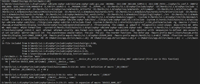
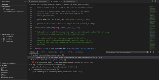
    Thanks for the reply. I have tried with the latest nrfConnect SDK and the following is the error when I open the sample application from the nrfConnect SDK and not a single change. It seems the sample is not compiling fine here.

  • Hi Simon,

    I have connected the logic analyzer to the spi pins and it seems the clock and spi pins are not working well in this case, I guess the spi initialization has some issue in code. Do you have any idea regarding this?

  • Thank you for the findings. Have you checked any of the other pins?

  • Yes, but the strange thing is there is no activity on these SPI pins? Do you know why this happens?

  • Could you please share the overlay file that was in use when you analyzed SPI?

    Does the overlay look anything like below? I realized &pinctrl might be missing. Please note that I have not tested the below overlay. I will try to do so later, although I do not have the physical display at hand.

    arduino_spi: &spi3 {
        compatible = "nordic,nrf-spim";
        status = "okay";
        cs-gpios = <&arduino_header 16 GPIO_ACTIVE_HIGH>; /* D10 */
        pinctrl-0 = < &spi3_default >;
        pinctrl-1 = < &spi3_sleep >;
        pinctrl-names = "default", "sleep";
    
        ls0xx: ls0xx@0 {
            compatible = "sharp,ls0xx";
            label = "LS0XX";
            spi-max-frequency = <2000000>;
            reg = <0>;
            width = <400>;
            height = <240>;
            extcomin-gpios = <&arduino_header 9 GPIO_ACTIVE_HIGH>; /* D3 */
            extcomin-frequency = <60>; /* required if extcomin-gpios is defined */
            disp-en-gpios = <&arduino_header 10 GPIO_ACTIVE_HIGH>; /* D4 */
        };
    };
    
    &pinctrl {     
        spi3_default: &spi3_default {
            group1 {
                psels = <NRF_PSEL(SPIM_SCK, 1, 15)>,  // D13
                        <NRF_PSEL(SPIM_MISO, 1, 14)>, // D12
                        <NRF_PSEL(SPIM_MOSI, 1, 13)>; // D11
            };
        };
    
        spi3_sleep: &spi3_sleep {
            group1 {
                psels = <NRF_PSEL(SPIM_SCK, 1, 15)>,  // D13
                        <NRF_PSEL(SPIM_MISO, 1, 14)>, // D12
                        <NRF_PSEL(SPIM_MOSI, 1, 13)>; // D11
                low-power-enable;
            };
        };
    };

    Muhammad said:
    the strange thing is there is no activity on these SPI pins?

    Is the recording from directly after reset? The other pins are also of interest as it would be good to verify whether the pins are correctly set up. I suppose the Disp pin is might be critical as it enables the display.

  • Sorry, something is wrong with the latest device tree. I will update this shortly.

Reply Children
  • Please try the following overlay:

    arduino_spi: &spi3 {
        compatible = "nordic,nrf-spim";
        status = "okay";
        cs-gpios = <&arduino_header 16 GPIO_ACTIVE_HIGH>; /* D10 */
        pinctrl-0 = < &spi3_default >;
        pinctrl-1 = < &spi3_sleep >;
        pinctrl-names = "default", "sleep";
    
        ls0xx: ls0xx@0 {
            compatible = "sharp,ls0xx";
            label = "LS0XX";
            spi-max-frequency = <2000000>;
            reg = <0>;
            width = <400>;
            height = <240>;
            extcomin-gpios = <&arduino_header 9 GPIO_ACTIVE_HIGH>; /* D3 */
            extcomin-frequency = <60>; /* required if extcomin-gpios is defined */
            disp-en-gpios = <&arduino_header 10 GPIO_ACTIVE_HIGH>; /* D4 */
        };
    };
    
    &pinctrl {     
        spi3_default: spi3_default {
            group1 {
                psels = <NRF_PSEL(SPIM_SCK, 1, 15)>,  // D13
                        <NRF_PSEL(SPIM_MISO, 1, 14)>, // D12
                        <NRF_PSEL(SPIM_MOSI, 1, 13)>; // D11
            };
        };
    
        spi3_sleep: spi3_sleep {
            group1 {
                psels = <NRF_PSEL(SPIM_SCK, 1, 15)>,  // D13
                        <NRF_PSEL(SPIM_MISO, 1, 14)>, // D12
                        <NRF_PSEL(SPIM_MOSI, 1, 13)>; // D11
                low-power-enable;
            };
        };
    };

    I have now tested this overlay and I am able to see activity on all pins.

  • Attached is the code that I tested, with the updated overlay:
    20221101-lvgl.zip

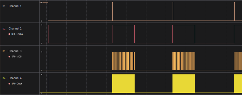
  • I assume the original poster left after finding a solution. Re: footnotes on page 8 of the LS027 datasheet, EXTMODE should be connected differently based on the state of EXCOMIN, and DISP determines if the display is on. I'm not sure if this is a problem related to some configuration used in that zipped project, an error with Zephyr's Sharp driver/shield, or a misunderstanding on my part, but the DISP pin is only ever briefly toggled after startup (see below, channel 1).

    This issue is solved specifically on the Adafruit breakout by disconnecting EXTMODE, EXCOMIN, and DISP altogether, as recommended in their user guide. Unfortunately I have no more information to provide for users in the future who may not be using the breakout, maybe I'll revisit this at some point once I've completed my project but for the time being the zip you posted does work properly and displays "Hello World" along with an incrementing counter at the bottom.

    Helsing, I really appreciate you having taken the time to help solve this problem with the poster. I was working on the same bringup process this week (Adafruit breakout for the LS027 + nRF52840 DK) and I hit a stuck point on Zephyr configurations before I found this thread, but the info and files provided here were enormously helpful in guiding me through.

  • Hi  ,

    Thanks for the details. I have been working on this with Zypher but no success, then I shifted to nRF5 SDK and the segger environment. Lately, I have imported the lvgl library to the segger environment and it compiles successfully. But again I am not able to turn on my display, when I debug the program it runs and I do receive some communication over the logic analyzer of the SPI pins but the program breaks after 5 to to 6 seconds when it goes to the handler in the while loop.  
    I think I need some opinion on the connections and working if you can please look at the code I am attaching and let me know what xyou think the issue could be as I think I am now very close but could not able to turn on the display. 
    For connections, I am using following

    CS --> P1.10

    MOSI-->P1.13

    CLK--> P1.14

    3V3-->VDD

    GND-->GND

    I have also tried connecting other pins like DISP, EXTMODE and EXCOMIN to VDD or GND with different combincations but no luck. Please check at your end if you can see what I am doing wrong, 

    /cfs-file/__key/communityserver-discussions-components-files/4/SDK_5F00_16.zip

    Looking forward to hear from you. Really appreciate the work.

    Thanks,

  • I can't really help you much from this point. The old nRF5 SDK was deprecated in favor of NCS + Zephyr before I had even touched a Nordic MCU, so I have no experience with it. But I must warn you, porting LVGL for a monochrome without Zephyr's drivers and integration is a nightmare. I know many people aren't the biggest fans of Zephyr's complexity and learning curve but it's a lifesaver in circumstances like these. It's not a simple port otherwise -- you'll likely need to write your own set pixel callback, rounder callback, make your own modifications to the lv conf file, add your own driver code (if it's not in the lv drivers GitHub repo), and only then will you be met with a glitchy screen and no support from LVGL's functionally-dead forums. At that point you'll desperately scan through the grand total of 2 LVGL monochrome port guides available, both of which also use deprecated code.

    Given that we have the exact same hardware, I can just about guarantee you'll have a functioning display if you switch back to NCS and use the zip file posted by helsing along with these connections:

    CS --> P1.12

    DI (MOSI) --> P1.13

    CLK --> P1.15

    VIN --> VDD

    GND --> GND

Related