Power consumption about LPUART

Hi,

I found a topic that discuss the LPUART power consumption.

 LPUAR 

In this discussion, it is mentioned that the power consumption of LPUART was introduce by GPIOTE IN, which is about 10~20uA.

From the old nRF SDK, we can set the hi_accuracy to false to reduce power consumption GPIOTE IN. But I don't found similar setting in NCS SDK.
typedef struct
{...
bool hi_accuracy : 1; /**< True when high accuracy (IN_EVENT) is used. */
...} nrfx_gpiote_in_config_t;

Also, I found another post two yeas ago discussing that Nordic may change the GPIOTE IN to the GPIO PORT event to reduce power consumption, Is there any up-to-date? 

 nRF9160 Sleep mode plus TWIS and LPUART 

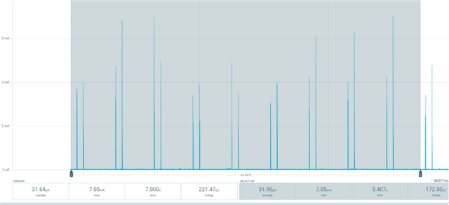
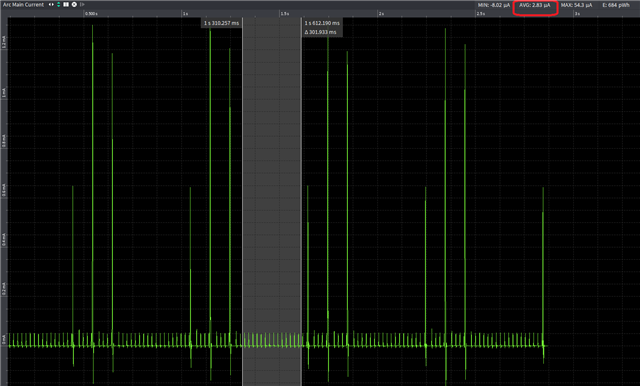
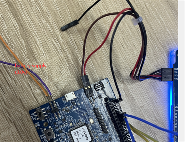
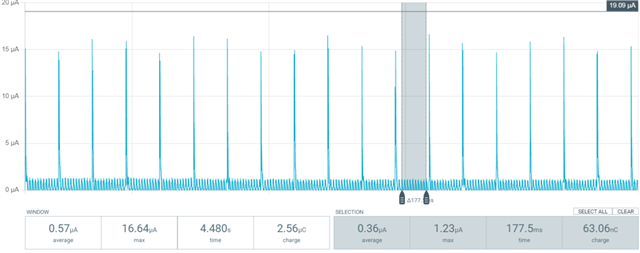
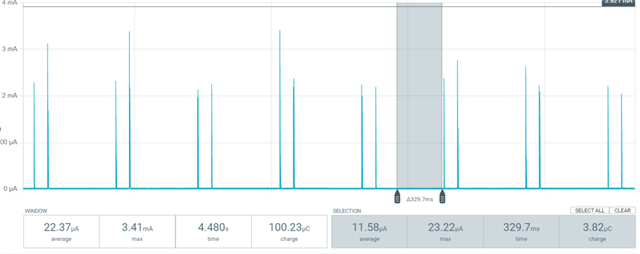
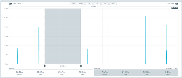
In addition to this, is there any way we can reduce the power consumption of the LPUART in the idle?  One of our products (NRF9160+NRF52832) uses the LPUART communication mechanism, and we found that idle power consumption is almost 35uA in IDLE state(nRF52832 is almost 19uA, and the nRF9160 is 15uA). We hope to reduce this power consumption.

Thanks,

Best Regards,

Hogen

Parents
  • Hi,

    Yes, you can configure the pins to use the PORT event instead of the IN event in NCS as well. This is done through the devicetree and the sense-edge-mask property

    https://developer.nordicsemi.com/nRF_Connect_SDK/doc/latest/zephyr/build/dts/api/bindings/gpio/nordic,nrf-gpio.html

    As an example you can configure pins 29 and 30 to use the PORT event in the following way, using an .overlay file:

    &gpio0 {
        sense-edge-mask = <((1 << 29) | (1 << 30))>;
    };

    If this is also applicable to the LPUART driver I will have to check, but I assume it is. Will test here and get back to you.

    Best regards,
    Stian

  • Hi, thanks for your suggestion. 

    I found it failed to send data after I added sense-edge-mask to the overload file. I test this on nrf/samples/peripheral/lpuart project. In addition, there power consumption is not change (20uA) after add the sense-edge-mask.

    00> [00:00:09.350,646] <err> app: Tx abortedit
    00> [00:00:11.350,860] <err> app: Tx aborted
    00> [00:00:13.351,074] <err> app: Tx aborted
    00> [00:00:15.351,287] <err> app: Tx aborted
    00> [00:00:17.351,501] <err> app: Tx aborted

    nrf52dk_nrf52832.overlay file:

    -------------

    &uart0 {
    rx-pin = <22>;
    tx-pin = <23>;
    /delete-property/ rts-pin;
    /delete-property/ cts-pin;
    compatible = "nordic,nrf-uarte";

    lpuart: nrf-sw-lpuart {
    compatible = "nordic,nrf-sw-lpuart";
    status = "okay";
    label = "LPUART";
    req-pin = <24>;
    rdy-pin = <25>;
    };
    };

    &gpio0 {
    sense-edge-mask = <((1 << 22) | (1 << 25))>;
    };

    &gpiote {
    interrupts = <6 NRF_DEFAULT_IRQ_PRIORITY>;
    };

  • Hi, I checked the current consumption on the nrf/sample/peripheral/lpuart sample, and seems like PORT event has already been implemented in the LPUART driver as default. The sample will draw about 3 uA in idle without any modifications.

    Which SDK version are you using? I tested this on NCS 2.1.1

    Best regards,
    Stian

  • Hi, Thanks for your help.

    I have re-tested based on NCSV2.1.2 today, on nrf52DK_52832 hardware.

    /resized-image/__size/640x480/__key/communityserver-discussions-components-files/4/pastedimage1668757421174v1.png

    My steps are as follows:

    1. Shorted TX (Pin 23) and RX (PIN 22) and req-pin (pin 24) and rdy-pin (pin 25) according to the README, and lte the demo do a loopback test.

    2.  I test the current without modifying the code, and found the average current is about 31uA. The demo sends data every 500+100 milliseconds. From the power consumption pulse diagram of PPK2, it looks like match the demo. 

    3. Then I enable RTT log output. I found the data send every 600ms. It looks like the code is working fine.

    CONFIG_LOG=y

    CONFIG_CONSOLE=y

    CONFIG_USE_SEGGER_RTT=y

    CONFIG_UART_CONSOLE=n

    4. I change the tx data interval from 500ms to 10second. The average current is drop to 21.63uA.  I selected the time between the two sending data, it seems that the idle state current seems to be 20.46uA.

    static void async(const struct device *lpuart)

    {        …

                  err = uart_tx(lpuart, txbuf, sizeof(txbuf), 10000);

                  __ASSERT(err == 0, "Failed to initiate transmission");

                  k_sleep(K_MSEC(10000));

                  uart_poll_out(lpuart, txbuf[0]);

                  k_sleep(K_MSEC(100));

    }

    Do you test on nrf52dk_nrf52832?  The 3uA current you tested is very small, can you share a screenshot of your current pulse graph?

    Best regard,

    Hogen

  • Hi, here is a screenshot of the unmodified example running on  a DK:

    I think there must be something wrong with your measurement setup. Can you please describe how you connect the PPK?

    The nRF52832 DK  can be a bit tricky to set up correctly for current measurements. The problem is that if you use the PPK in ampere meter mode and measure the current through the P22 header, there will be noise from the USB and regulators on the DK, giving you an additional current of about 10-20 uA. The workaround is to unplug the USB cable and power the DK from a battery or a stable voltage supply on P21 at 3V.

    Alternatively, you can use the PPK in source meter mode, connecting VOUT to P22 (the pin closest to the debug out header), and GND to GND. Leaving the USB cable connected. The problem with this setup is that the voltage output from the PPK has to match VDD on the DK exactly, which is around 2.7V. Otherwise there will be leakage through the SWD and/or the nRESET lines back to the debugging chip which is powered from VDD.

    To test the measurement setup you can put the chip to system off mode.

    Just add NRF_POWER->SYSTEMOFF = 1; to the beginning of main. You should now see around 0.3 uA. (in system off it is important to measure over several seconds, and use the average current over this whole period in order to get the correct current, since there will be spikes every ~500ms which are part of the system OFF current.)

    EDIT:

    You can check out this guide written for the nRF91 on how to use either Source meter mode, or ampere meter mode. It should be similar for the nRF52832 DK, except that the voltage in source meter mode should be set to 2.7V

Reply
  • Hi, here is a screenshot of the unmodified example running on  a DK:

    I think there must be something wrong with your measurement setup. Can you please describe how you connect the PPK?

    The nRF52832 DK  can be a bit tricky to set up correctly for current measurements. The problem is that if you use the PPK in ampere meter mode and measure the current through the P22 header, there will be noise from the USB and regulators on the DK, giving you an additional current of about 10-20 uA. The workaround is to unplug the USB cable and power the DK from a battery or a stable voltage supply on P21 at 3V.

    Alternatively, you can use the PPK in source meter mode, connecting VOUT to P22 (the pin closest to the debug out header), and GND to GND. Leaving the USB cable connected. The problem with this setup is that the voltage output from the PPK has to match VDD on the DK exactly, which is around 2.7V. Otherwise there will be leakage through the SWD and/or the nRESET lines back to the debugging chip which is powered from VDD.

    To test the measurement setup you can put the chip to system off mode.

    Just add NRF_POWER->SYSTEMOFF = 1; to the beginning of main. You should now see around 0.3 uA. (in system off it is important to measure over several seconds, and use the average current over this whole period in order to get the correct current, since there will be spikes every ~500ms which are part of the system OFF current.)

    EDIT:

    You can check out this guide written for the nRF91 on how to use either Source meter mode, or ampere meter mode. It should be similar for the nRF52832 DK, except that the voltage in source meter mode should be set to 2.7V

Children
  • Hi,

    Thanks for your clarification. I have change the USB to battery supply, and using ampere meter mode to measure the current. 

    When I add NRF_POWER->SYSTEMOFF = 1 to the beginning of main, the average current is 0.57uA.

    When I remove NRF_POWER->SYSTEMOFF = 1 in LPUART, the idle current is 11.58uA.

    I also do test on 9160dk, the result is similar.

    It looks like that GPIO PORT event in my project doesn't take effect. Can you share the zephyr.dts in \build_nrf52dk_nrf52832\zephyr directory, and which commit id are you testing based on?

    BR

    Hogen

  • Hi, I think I know what the problem is. I was testing this on a nRF52840 DK, and the 840 is configured to use UART1, while the nRF52832 is using UART0. The prj.conf file sets only UART1 to low power, but that will not take effect on the nRF52832, since it is using UART0. This should have been fixed in the boards/nrf52dk_nrf52832.conf file, but it's missing CONFIG_UART_0_NRF_ASYNC_LOW_POWER=y.

    Try to add this config and see if that fixes the issue. I tested this now on a PCA10040, and I get 2.7 uA during idle:

    Otherwise, your measurement setup looks good now, and the system off code verifies that the PPK is showing the right current.

    EDIT:

    I also tested on a nRF91 DK, and this is already configured correctly, since it is using UART1. I think the best way to measure on a nRF91 DK is to use the PPK in source meter mode, and set the voltage output to 3.3V or higher (up to 5V). The connections should look as described in this guide, under the SMU mode section.

    Best regards,
    Stian

  • Hi Stian,

    Add CONFIG_UART_0_NRF_ASYNC_LOW_POWER=y fixed my problem.Thank you very much.

Related