TWI Scanner Example is not Working in Custom Board (NRF52840)

Hi,

1. Here I am using the nrf52840 in my customized board, in parallel I have nrf52840 dev board. In My custom Onboard debugger is not available so I am using SWD to load the program from NRF52840 DK board to Custom Board (NRF52840).

2. I am loading TWI Scanner Example program to my custom board, from that nothing is displayed on terminal, But If I am flashing same TWI scanner example to Dev boards its working and its displaying like TWI Scanner Started But in my custom board nothing is displayed. 

3. I have mention I2C pin as P0.06 & P0.07, and also I have mention UART in my custom board as P1.11(TX), P1.12(RX), P1.10(CTS), P0.30(RTS).

My doubt why log is not displaying anything in my custom board. and one more doubt also whether I have to mention custom board UART pins in TWI Scanner Example??

I have raised this questions in my previous thread, there is no reply that's why I posed this thread. Please anyone help me on this. I am waiting for your quick response...

Thanks in advance.

Parents
  • 2. I am loading TWI Scanner Example program to my custom board, from that nothing is displayed on terminal, But If I am flashing same TWI scanner example to Dev boards its working and its displaying like TWI Scanner Started But in my custom board nothing is displayed. 

    Jansi, 

    Please connect the TWI pins to the logic analyzer or similar and see if there are any data TWI data being transmitted/received on these pins.

    Please notice the TWI is not used in NRF_LOG. NRF_LOGGER module only uses UART/RTT or Flash as the backend and not TWI. The TWI data that you are transmitting/receiving in your firmware cannot be seen in the terminal, but the NRF_LOG statements that you have in your firmware should be transmitted on the UART pins and using your TTL/FTDI connections, you should be able to redirect them to your computer USB board into a virtual com port. 

    1. Please check on your UART pins using a logic analyzer to see if there is any data that is being transmitted on uart pins? If you can see the expected data on the pins using the logic analyzer,
    2. then check to see the FTDI connections and then
    3. check if you have configured the COM terminal on the computer with correct baudrate and other settings like flow control etc..

    If you still have problem seeing your firmware NRF_LOG data on serial terminal then post me the snapshots of

    1. Check the backend you are using for the firmware in your custom board. I am assuming you are using uart as backend.
    2. Logic logic analyzer to all four uart pins and take a snapshot of Logic analyzer data showing that the NRF_LOG data is being transmitted to the UART pins. 
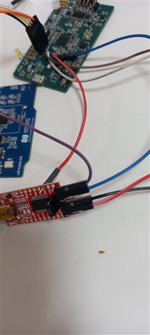
    3. your FTDI connections picture
    4. Your com port terminal settings matching the serial backend you use. Like baudrate, stop/parity bit and hardware flow control setting.

    This was supposed to be a very simple task to see your serial data of your custom board. Not sure what is wrong without seeing your logic analyzer snapshots.

  • Hi,

    I will share some screenshot related to my previous thread questions in below,

    1. Check the backend you are using for the firmware in your custom board. I am assuming you are using uart as backend.---> Yes I am using UART as backend like 

    Ex:-

    #ifndef NRFX_UART_ENABLED
    #define NRFX_UART_ENABLED 1
    #endif

    #ifndef NRF_LOG_BACKEND_UART_ENABLED
    #define NRF_LOG_BACKEND_UART_ENABLED 1
    #endif

    and 

    #ifndef NRF_LOG_BACKEND_RTT_ENABLED
    #define NRF_LOG_BACKEND_RTT_ENABLED 0
    #endif

    2. I have checked that TWI pins in oscilloscope, I did not find any data for both SCL pins , SDA pins and also UART pins.

    3. In below attachment I will share the FTDI connector connections

    and also I will share my main.c and pca10056.h and sdk.config.h

    Please help me on this. Thanks in advance.

    Fullscreen
    1
    2
    3
    4
    5
    6
    7
    8
    9
    10
    11
    12
    13
    14
    15
    16
    17
    18
    19
    20
    21
    /**
    * Copyright (c) 2016 - 2018, Nordic Semiconductor ASA
    *
    * All rights reserved.
    *
    * Redistribution and use in source and binary forms, with or without modification,
    * are permitted provided that the following conditions are met:
    *
    * 1. Redistributions of source code must retain the above copyright notice, this
    * list of conditions and the following disclaimer.
    *
    * 2. Redistributions in binary form, except as embedded into a Nordic
    * Semiconductor ASA integrated circuit in a product or a software update for
    * such product, must reproduce the above copyright notice, this list of
    * conditions and the following disclaimer in the documentation and/or other
    * materials provided with the distribution.
    *
    * 3. Neither the name of Nordic Semiconductor ASA nor the names of its
    * contributors may be used to endorse or promote products derived from this
    * software without specific prior written permission.
    *
    XXXXXXXXXXXXXXXXXXXXXXXXXXXXXXXXXXXXXXXXXXXXXXXXXX

  • Jansi, Please read other devzone post regarding why the UART is not able to transmit data to the pins. This does not seem to be an issue with the FTDI converter or your connections, the issue seems more basic that the UART on your custom board is not sending any bytes at all at the source level.

  • Hi,

    Now I am getting some data on RTT viewer, not in termite. But now i am not getting any data for I2C .I have mention my slave address, its detecting the address also, and configuration register I calculated, mention in code also. Is there any register need to mention?. Can you please tell me how to calculate the register value in datasheets (ex:- I am using ADC - MCP3428).

    I will attach my recent code in below attachment and datasheet. can you please help me on this.

    Fullscreen
    1
    2
    3
    4
    5
    6
    7
    8
    9
    10
    11
    12
    13
    14
    15
    16
    17
    18
    19
    20
    21
    #include <stdbool.h>
    #include <stdint.h>
    #include <string.h>
    #include "nrf.h"
    #include <stdio.h>
    #include "boards.h"
    #include "app_util_platform.h"
    #include "app_error.h"
    #include "nrf_drv_twi.h"
    #include "nrf_delay.h"
    #include "SEGGER_RTT.h"
    #include "nrf_log.h"
    #include "nrf_log_ctrl.h"
    #include "nrf_log_default_backends.h"
    #define TWI_SCL_M NRF_GPIO_PIN_MAP(0,6)
    #define TWI_SDA_M NRF_GPIO_PIN_MAP(0,7)
    XXXXXXXXXXXXXXXXXXXXXXXXXXXXXXXXXXXXXXXXXXXXXXXXXX

    https://www.mouser.in/datasheet/2/268/22226a-81911.pdf..

    Thanks in advance Mr. Susheel.

  • I am not familiar with this external sensor Jansi. I can't help you with that as it is not possible for us to debug external sensor related issues. 

  • Hi,

    I have one doubt.

    1. In my custom board schematic having temperature sensor that part no is TMP100 using I2C.. But I am using External Temperature sensor that is SHT25, this SHT25 is not present in my board. so my question is it possible to implement external temperature to my board???

    Thanks in advance.

  • Hi,

    I am waiting for your reply.

Reply Children
  • Hello,

    I have implemented the SHT25 temperature sensor with ardiuno, now i want to implement this code and register configuration in nrf52840. can you please tell me how to implement this register in NRF.

    Thanks in advance.

    I will share the ardiuno code in below, Please help me on this, In which statement or function I have to read & write this register.

    #include<Wire.h>
    // SHT25 I2C address is 0x40(64)
    #define Addr 0x40
    void setup()
    {
    // Initialise I2C communication as MASTER
    Wire.begin();
    // Initialise serial communication, set baud rate = 9600
    Serial.begin(9600);
    delay(300);
    }
    void loop()
    {
    unsigned int data[2];
    // Start I2C transmission
    Wire.beginTransmission(Addr);
    // Send humidity measurement command, NO HOLD master
    Wire.write(0xF5);
    // Stop I2C transmission
    Wire.endTransmission();
    delay(500);
    // Request 2 bytes of data
    Wire.requestFrom(Addr, 2);
    // Read 2 bytes of data
    // humidity msb, humidity lsb
    if(Wire.available() == 2)
    {
    data[0] = Wire.read();
    data[1] = Wire.read();
    // Convert the data
    float humidity = (((data[0] * 256.0 + data[1]) * 125.0) / 65536.0) - 6;
    // Output data to Serial Monitor
    Serial.print("Relative Humidity :");
    Serial.print(humidity);
    Serial.println(" %RH");
    }
    // Start I2C transmission
    Wire.beginTransmission(Addr);
    // Send temperature measurement command, NO HOLD master
    Wire.write(0xF3);
    // Stop I2C transmission
    Wire.endTransmission();
    delay(500);
    // Request 2 bytes of data
    Wire.requestFrom(Addr, 2);
    // Read 2 bytes of data
    // temp msb, temp lsb
    if(Wire.available() == 2)
    {
    data[0] = Wire.read();
    data[1] = Wire.read();
    // Convert the data
    float cTemp = (((data[0] * 256.0 + data[1]) * 175.72) / 65536.0) - 46.85;
    float fTemp = (cTemp * 1.8) + 32;
    // Output data to Serial Monitor
    Serial.print("Temperature in Celsius :");
    Serial.print(cTemp);
    Serial.println(" C");
    Serial.print("Temperature in Fahrenheit :");
    Serial.print(fTemp);
    Serial.println(" F");
    }
    delay(300);
    }