TWI Scanner Example is not Working in Custom Board (NRF52840)

Hi,

1. Here I am using the nrf52840 in my customized board, in parallel I have nrf52840 dev board. In My custom Onboard debugger is not available so I am using SWD to load the program from NRF52840 DK board to Custom Board (NRF52840).

2. I am loading TWI Scanner Example program to my custom board, from that nothing is displayed on terminal, But If I am flashing same TWI scanner example to Dev boards its working and its displaying like TWI Scanner Started But in my custom board nothing is displayed. 

3. I have mention I2C pin as P0.06 & P0.07, and also I have mention UART in my custom board as P1.11(TX), P1.12(RX), P1.10(CTS), P0.30(RTS).

My doubt why log is not displaying anything in my custom board. and one more doubt also whether I have to mention custom board UART pins in TWI Scanner Example??

I have raised this questions in my previous thread, there is no reply that's why I posed this thread. Please anyone help me on this. I am waiting for your quick response...

Thanks in advance.

Parents
  • 2. I am loading TWI Scanner Example program to my custom board, from that nothing is displayed on terminal, But If I am flashing same TWI scanner example to Dev boards its working and its displaying like TWI Scanner Started But in my custom board nothing is displayed. 

    Jansi, 

    Please connect the TWI pins to the logic analyzer or similar and see if there are any data TWI data being transmitted/received on these pins.

    Please notice the TWI is not used in NRF_LOG. NRF_LOGGER module only uses UART/RTT or Flash as the backend and not TWI. The TWI data that you are transmitting/receiving in your firmware cannot be seen in the terminal, but the NRF_LOG statements that you have in your firmware should be transmitted on the UART pins and using your TTL/FTDI connections, you should be able to redirect them to your computer USB board into a virtual com port. 

    1. Please check on your UART pins using a logic analyzer to see if there is any data that is being transmitted on uart pins? If you can see the expected data on the pins using the logic analyzer,
    2. then check to see the FTDI connections and then
    3. check if you have configured the COM terminal on the computer with correct baudrate and other settings like flow control etc..

    If you still have problem seeing your firmware NRF_LOG data on serial terminal then post me the snapshots of

    1. Check the backend you are using for the firmware in your custom board. I am assuming you are using uart as backend.
    2. Logic logic analyzer to all four uart pins and take a snapshot of Logic analyzer data showing that the NRF_LOG data is being transmitted to the UART pins. 
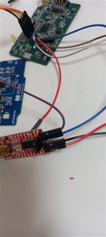
    3. your FTDI connections picture
    4. Your com port terminal settings matching the serial backend you use. Like baudrate, stop/parity bit and hardware flow control setting.

    This was supposed to be a very simple task to see your serial data of your custom board. Not sure what is wrong without seeing your logic analyzer snapshots.

  • Hi,

    I will share some screenshot related to my previous thread questions in below,

    1. Check the backend you are using for the firmware in your custom board. I am assuming you are using uart as backend.---> Yes I am using UART as backend like 

    Ex:-

    #ifndef NRFX_UART_ENABLED
    #define NRFX_UART_ENABLED 1
    #endif

    #ifndef NRF_LOG_BACKEND_UART_ENABLED
    #define NRF_LOG_BACKEND_UART_ENABLED 1
    #endif

    and 

    #ifndef NRF_LOG_BACKEND_RTT_ENABLED
    #define NRF_LOG_BACKEND_RTT_ENABLED 0
    #endif

    2. I have checked that TWI pins in oscilloscope, I did not find any data for both SCL pins , SDA pins and also UART pins.

    3. In below attachment I will share the FTDI connector connections

    and also I will share my main.c and pca10056.h and sdk.config.h

    Please help me on this. Thanks in advance.

    /**
     * Copyright (c) 2016 - 2018, Nordic Semiconductor ASA
     * 
     * All rights reserved.
     * 
     * Redistribution and use in source and binary forms, with or without modification,
     * are permitted provided that the following conditions are met:
     * 
     * 1. Redistributions of source code must retain the above copyright notice, this
     *    list of conditions and the following disclaimer.
     * 
     * 2. Redistributions in binary form, except as embedded into a Nordic
     *    Semiconductor ASA integrated circuit in a product or a software update for
     *    such product, must reproduce the above copyright notice, this list of
     *    conditions and the following disclaimer in the documentation and/or other
     *    materials provided with the distribution.
     * 
     * 3. Neither the name of Nordic Semiconductor ASA nor the names of its
     *    contributors may be used to endorse or promote products derived from this
     *    software without specific prior written permission.
     * 
     * 4. This software, with or without modification, must only be used with a
     *    Nordic Semiconductor ASA integrated circuit.
     * 
     * 5. Any software provided in binary form under this license must not be reverse
     *    engineered, decompiled, modified and/or disassembled.
     * 
     * THIS SOFTWARE IS PROVIDED BY NORDIC SEMICONDUCTOR ASA "AS IS" AND ANY EXPRESS
     * OR IMPLIED WARRANTIES, INCLUDING, BUT NOT LIMITED TO, THE IMPLIED WARRANTIES
     * OF MERCHANTABILITY, NONINFRINGEMENT, AND FITNESS FOR A PARTICULAR PURPOSE ARE
     * DISCLAIMED. IN NO EVENT SHALL NORDIC SEMICONDUCTOR ASA OR CONTRIBUTORS BE
     * LIABLE FOR ANY DIRECT, INDIRECT, INCIDENTAL, SPECIAL, EXEMPLARY, OR
     * CONSEQUENTIAL DAMAGES (INCLUDING, BUT NOT LIMITED TO, PROCUREMENT OF SUBSTITUTE
     * GOODS OR SERVICES; LOSS OF USE, DATA, OR PROFITS; OR BUSINESS INTERRUPTION)
     * HOWEVER CAUSED AND ON ANY THEORY OF LIABILITY, WHETHER IN CONTRACT, STRICT
     * LIABILITY, OR TORT (INCLUDING NEGLIGENCE OR OTHERWISE) ARISING IN ANY WAY OUT
     * OF THE USE OF THIS SOFTWARE, EVEN IF ADVISED OF THE POSSIBILITY OF SUCH DAMAGE.
     * 
     */
    #ifndef PCA10056_H
    #define PCA10056_H
    
    #ifdef __cplusplus
    extern "C" {
    #endif
    
    #include "nrf_gpio.h"
    
    // LEDs definitions for PCA10056
    #define LEDS_NUMBER    4
    
    #define LED_1          NRF_GPIO_PIN_MAP(0,13)
    #define LED_2          NRF_GPIO_PIN_MAP(0,14)
    #define LED_3          NRF_GPIO_PIN_MAP(0,15)
    #define LED_4          NRF_GPIO_PIN_MAP(0,16)
    #define LED_START      LED_1
    #define LED_STOP       LED_4
    
    #define LEDS_ACTIVE_STATE 0
    
    #define LEDS_LIST { LED_1, LED_2, LED_3, LED_4 }
    
    #define LEDS_INV_MASK  LEDS_MASK
    
    #define BSP_LED_0      13
    #define BSP_LED_1      14
    #define BSP_LED_2      15
    #define BSP_LED_3      16
    
    #define BUTTONS_NUMBER 4
    
    #define BUTTON_1       11
    #define BUTTON_2       12
    #define BUTTON_3       24
    #define BUTTON_4       25
    #define BUTTON_PULL    NRF_GPIO_PIN_PULLUP
    
    #define BUTTONS_ACTIVE_STATE 0
    
    #define BUTTONS_LIST { BUTTON_1, BUTTON_2, BUTTON_3, BUTTON_4 }
    
    #define BSP_BUTTON_0   BUTTON_1
    #define BSP_BUTTON_1   BUTTON_2
    #define BSP_BUTTON_2   BUTTON_3
    #define BSP_BUTTON_3   BUTTON_4
    
    #define RX_PIN_NUMBER   NRF_GPIO_PIN_MAP(1,3)
    #define TX_PIN_NUMBER   NRF_GPIO_PIN_MAP(1,2)
    #define CTS_PIN_NUMBER  NRF_GPIO_PIN_MAP(0,9)
    #define RTS_PIN_NUMBER  NRF_GPIO_PIN_MAP(0,10)
    #define HWFC           true
    
    #define BSP_QSPI_SCK_PIN   19
    #define BSP_QSPI_CSN_PIN   17
    #define BSP_QSPI_IO0_PIN   20
    #define BSP_QSPI_IO1_PIN   21
    #define BSP_QSPI_IO2_PIN   22
    #define BSP_QSPI_IO3_PIN   23
    
    
    // serialization APPLICATION board - temp. setup for running serialized MEMU tests
    #define SER_APP_RX_PIN              NRF_GPIO_PIN_MAP(1,13)    // UART RX pin number.
    #define SER_APP_TX_PIN              NRF_GPIO_PIN_MAP(1,14)    // UART TX pin number.
    #define SER_APP_CTS_PIN             NRF_GPIO_PIN_MAP(0,2)     // UART Clear To Send pin number.
    #define SER_APP_RTS_PIN             NRF_GPIO_PIN_MAP(1,15)    // UART Request To Send pin number.
    
    #define SER_APP_SPIM0_SCK_PIN       NRF_GPIO_PIN_MAP(0,27)     // SPI clock GPIO pin number.
    #define SER_APP_SPIM0_MOSI_PIN      NRF_GPIO_PIN_MAP(0,2)      // SPI Master Out Slave In GPIO pin number
    #define SER_APP_SPIM0_MISO_PIN      NRF_GPIO_PIN_MAP(0,26)     // SPI Master In Slave Out GPIO pin number
    #define SER_APP_SPIM0_SS_PIN        NRF_GPIO_PIN_MAP(1,13)     // SPI Slave Select GPIO pin number
    #define SER_APP_SPIM0_RDY_PIN       NRF_GPIO_PIN_MAP(1,15)     // SPI READY GPIO pin number
    #define SER_APP_SPIM0_REQ_PIN       NRF_GPIO_PIN_MAP(1,14)     // SPI REQUEST GPIO pin number
    
    // serialization CONNECTIVITY board
    #define SER_CON_RX_PIN              NRF_GPIO_PIN_MAP(1,14)    // UART RX pin number.
    #define SER_CON_TX_PIN              NRF_GPIO_PIN_MAP(1,13)    // UART TX pin number.
    #define SER_CON_CTS_PIN             NRF_GPIO_PIN_MAP(1,15)    // UART Clear To Send pin number. Not used if HWFC is set to false.
    #define SER_CON_RTS_PIN             NRF_GPIO_PIN_MAP(0,2)     // UART Request To Send pin number. Not used if HWFC is set to false.
    
    
    #define SER_CON_SPIS_SCK_PIN        NRF_GPIO_PIN_MAP(0,27)    // SPI SCK signal.
    #define SER_CON_SPIS_MOSI_PIN       NRF_GPIO_PIN_MAP(0,2)     // SPI MOSI signal.
    #define SER_CON_SPIS_MISO_PIN       NRF_GPIO_PIN_MAP(0,26)    // SPI MISO signal.
    #define SER_CON_SPIS_CSN_PIN        NRF_GPIO_PIN_MAP(1,13)    // SPI CSN signal.
    #define SER_CON_SPIS_RDY_PIN        NRF_GPIO_PIN_MAP(1,15)    // SPI READY GPIO pin number.
    #define SER_CON_SPIS_REQ_PIN        NRF_GPIO_PIN_MAP(1,14)    // SPI REQUEST GPIO pin number.
    
    #define SER_CONN_CHIP_RESET_PIN     NRF_GPIO_PIN_MAP(1,1)    // Pin used to reset connectivity chip
    
    // Arduino board mappings
    //#define ARDUINO_SCL_PIN             NRF_GPIO_PIN_MAP(0,6)    // SCL signal pin
    //#define ARDUINO_SDA_PIN             NRF_GPIO_PIN_MAP(0,7)   // SDA signal pin
    //#define ARDUINO_AREF_PIN            2     // Aref pin
    
    #define TWI_SCL_M  NRF_GPIO_PIN_MAP(0,6)
    #define TWI_SDL_M  NRF_GPIO_PIN_MAP(0,7)
    
    #define ARDUINO_13_PIN              NRF_GPIO_PIN_MAP(1, 15)  // Digital pin 13
    #define ARDUINO_12_PIN              NRF_GPIO_PIN_MAP(1, 14)  // Digital pin 12
    #define ARDUINO_11_PIN              NRF_GPIO_PIN_MAP(1, 13)  // Digital pin 11
    #define ARDUINO_10_PIN              NRF_GPIO_PIN_MAP(1, 12)  // Digital pin 10
    #define ARDUINO_9_PIN               NRF_GPIO_PIN_MAP(1, 11)  // Digital pin 9
    #define ARDUINO_8_PIN               NRF_GPIO_PIN_MAP(1, 10)  // Digital pin 8
    
    #define ARDUINO_7_PIN               NRF_GPIO_PIN_MAP(1, 8) // Digital pin 7
    #define ARDUINO_6_PIN               NRF_GPIO_PIN_MAP(1, 7) // Digital pin 6
    #define ARDUINO_5_PIN               NRF_GPIO_PIN_MAP(1, 6) // Digital pin 5
    #define ARDUINO_4_PIN               NRF_GPIO_PIN_MAP(1, 5) // Digital pin 4
    #define ARDUINO_3_PIN               NRF_GPIO_PIN_MAP(1, 4) // Digital pin 3
    #define ARDUINO_2_PIN               NRF_GPIO_PIN_MAP(1, 3) // Digital pin 2
    #define ARDUINO_1_PIN               NRF_GPIO_PIN_MAP(1, 2) // Digital pin 1
    #define ARDUINO_0_PIN               NRF_GPIO_PIN_MAP(1, 1) // Digital pin 0
    
    #define ARDUINO_A0_PIN              3     // Analog channel 0
    #define ARDUINO_A1_PIN              4     // Analog channel 1
    #define ARDUINO_A2_PIN              28    // Analog channel 2
    #define ARDUINO_A3_PIN              29    // Analog channel 3
    #define ARDUINO_A4_PIN              30    // Analog channel 4
    #define ARDUINO_A5_PIN              31    // Analog channel 5
    
    
    #ifdef __cplusplus
    }
    #endif
    
    #endif // PCA10056_H
    

  • Hi,

    Now I am getting some data on RTT viewer, not in termite. But now i am not getting any data for I2C .I have mention my slave address, its detecting the address also, and configuration register I calculated, mention in code also. Is there any register need to mention?. Can you please tell me how to calculate the register value in datasheets (ex:- I am using ADC - MCP3428).

    I will attach my recent code in below attachment and datasheet. can you please help me on this.

    #include <stdbool.h>
    #include <stdint.h>
    #include <string.h>
    #include "nrf.h"
    
    #include <stdio.h>
    #include "boards.h"
    #include "app_util_platform.h"
    #include "app_error.h"
    #include "nrf_drv_twi.h"
    #include "nrf_delay.h"
    #include "SEGGER_RTT.h"
    
    #include "nrf_log.h"
    #include "nrf_log_ctrl.h"
    #include "nrf_log_default_backends.h"
    
    
    #define TWI_SCL_M NRF_GPIO_PIN_MAP(0,6)
    #define TWI_SDA_M NRF_GPIO_PIN_MAP(0,7)
    
    #define ADC_ADDRESS_LEN 1
    #define Slave_Address 0xD0
    //#define ADC_WHO_AM_I   0x68U
    
    #define REG_CFG          0x90
    #define REG_RESET        0x06
    #define REG_LATCH        0x04
    #define REG_CONV         0x08
    #define REG_Write        0x06
    #define REG_Read         0x06
    
      uint8_t sample_data = 0x00; // sample data initialized with 0 value.
    
    /* TWI instance ID. */
    #define TWI_INSTANCE_ID     0
    
    
    //#define LM75B_REG_TEMP      0x00U
    //#define LM75B_REG_CONF      0x01U
    //#define LM75B_REG_THYST     0x02U
    //#define LM75B_REG_TOS       0x03U


    /* Mode for LM75B. */
    #define CONTINUOUS_CONVERSION_MODE 0
    
    /* Indicates if operation on TWI has ended. */
    static volatile bool m_xfer_done = false;
    
    /* TWI instance. */
    static const nrf_drv_twi_t m_twi = NRF_DRV_TWI_INSTANCE(TWI_INSTANCE_ID);
    
    /* Buffer for samples read from temperature sensor. */
    static uint8_t m_sample;
    
    /**
     * @brief Function for setting active mode on MMA7660 accelerometer.
     */
    void LM75B_set_mode(void)
    {
        ret_code_t err_code;
    
        /* Writing to LM75B_REG_CONF "0" set temperature sensor in NORMAL mode. */
        uint8_t reg[2] = {REG_CFG, CONTINUOUS_CONVERSION_MODE};
    	//	memcpy(&reg,m_sample,ADC_ADDRESS_LEN);
        err_code = nrf_drv_twi_tx(&m_twi, Slave_Address, reg, sizeof(reg), false);
        APP_ERROR_CHECK(err_code);
        while (m_xfer_done == false);
    
        /* Writing to pointer byte. */
      //  reg[0] =0x00;
      //  m_xfer_done = false;
       // err_code = nrf_drv_twi_tx(&m_twi, Slave_Address, reg, 1, false);
       // APP_ERROR_CHECK(err_code);
        //while (m_xfer_done == false);
    }
    
    /**
     * @brief Function for handling data from temperature sensor.
     *
     * @param[in] temp          Temperature in Celsius degrees read from sensor.
     */
    __STATIC_INLINE void data_handler(uint8_t temp)
    {
        NRF_LOG_INFO("ADC Value is: %d\r\n.", temp);
    }
    
    /**
     * @brief TWI events handler.
     */
    void twi_handler(nrf_drv_twi_evt_t const * p_event, void * p_context)
    {
        switch (p_event->type)
        {
            case NRF_DRV_TWI_EVT_DONE:
                if (p_event->xfer_desc.type == NRF_DRV_TWI_XFER_RX)
                {
                    data_handler(m_sample);
                }
                m_xfer_done = true;
                break;
            default:
                break;
        }
    }
    
    /**
     * @brief UART initialization.
     */
    void twi_init (void)
    {
        ret_code_t err_code;
    
        const nrf_drv_twi_config_t twi_lm75b_config = {
           .scl                = TWI_SCL_M,
           .sda                = TWI_SDA_M,
           .frequency          = NRF_DRV_TWI_FREQ_100K,
           .interrupt_priority = APP_IRQ_PRIORITY_HIGH,
           .clear_bus_init     = false
        };
    
        err_code = nrf_drv_twi_init(&m_twi, &twi_lm75b_config, twi_handler, NULL);
        APP_ERROR_CHECK(err_code);
    
        nrf_drv_twi_enable(&m_twi);
    }
    
    /**
     * @brief Function for reading data from temperature sensor.
     */
    static void read_sensor_data()
    {
    	
    	  ret_code_t err_code;
        m_xfer_done = false;
    //	uint8_t reg=0x00;
      //err_code = nrf_drv_twi_tx(&m_twi, Slave_Address, &reg, sizeof(reg), false);
        //APP_ERROR_CHECK(err_code);
        /* Read 1 byte from the specified address - skip 3 bits dedicated for fractional part of temperature. */
        err_code = nrf_drv_twi_rx(&m_twi, Slave_Address, &m_sample, sizeof(m_sample));
        APP_ERROR_CHECK(err_code);
    	    NRF_LOG_INFO(0, "%d ", m_sample);
    
    }
    
    /**
     * @brief Function for main application entry.
     */
    int main(void)
    {
    	
    	  ret_code_t err_code; // a variable to hold error code value
    
        APP_ERROR_CHECK(NRF_LOG_INIT(NULL));
        NRF_LOG_DEFAULT_BACKENDS_INIT();
    
        NRF_LOG_INFO("\r\nTWI sensor example started.");
        NRF_LOG_FLUSH();
        twi_init();
        LM75B_set_mode();
    	  NRF_LOG_INFO(0, "Printing over RTT!\r\n");


    	//  err_code = nrf_drv_twi_rx(&m_twi, Slave_Address, &sample_data, sizeof(sample_data));
    
    	 //if(err_code == NRF_SUCCESS) // if reading data was successful
      //{
    
        //NRF_LOG_INFO("Successfully detected a device at address: 0x%x", Slave_Address); // let the users know its working
      
        //}
    	//else
    //	{
    	//	NRF_LOG_INFO("No device found");
    	//}
        while (true)
        {
         //   nrf_delay_ms(500);
    
            do
            {
                __WFE();
            }while (m_xfer_done == false);
    
            read_sensor_data();
            NRF_LOG_FLUSH();
        }
    }
    
    /** @} */
    

    https://www.mouser.in/datasheet/2/268/22226a-81911.pdf..

    Thanks in advance Mr. Susheel.

  • I am not familiar with this external sensor Jansi. I can't help you with that as it is not possible for us to debug external sensor related issues. 

  • Hi,

    I have one doubt.

    1. In my custom board schematic having temperature sensor that part no is TMP100 using I2C.. But I am using External Temperature sensor that is SHT25, this SHT25 is not present in my board. so my question is it possible to implement external temperature to my board???

    Thanks in advance.

  • Hello,

    I have implemented the SHT25 temperature sensor with ardiuno, now i want to implement this code and register configuration in nrf52840. can you please tell me how to implement this register in NRF.

    Thanks in advance.

    I will share the ardiuno code in below, Please help me on this, In which statement or function I have to read & write this register.

    #include<Wire.h>
    // SHT25 I2C address is 0x40(64)
    #define Addr 0x40
    void setup()
    {
    // Initialise I2C communication as MASTER
    Wire.begin();
    // Initialise serial communication, set baud rate = 9600
    Serial.begin(9600);
    delay(300);
    }
    void loop()
    {
    unsigned int data[2];
    // Start I2C transmission
    Wire.beginTransmission(Addr);
    // Send humidity measurement command, NO HOLD master
    Wire.write(0xF5);
    // Stop I2C transmission
    Wire.endTransmission();
    delay(500);
    // Request 2 bytes of data
    Wire.requestFrom(Addr, 2);
    // Read 2 bytes of data
    // humidity msb, humidity lsb
    if(Wire.available() == 2)
    {
    data[0] = Wire.read();
    data[1] = Wire.read();
    // Convert the data
    float humidity = (((data[0] * 256.0 + data[1]) * 125.0) / 65536.0) - 6;
    // Output data to Serial Monitor
    Serial.print("Relative Humidity :");
    Serial.print(humidity);
    Serial.println(" %RH");
    }
    // Start I2C transmission
    Wire.beginTransmission(Addr);
    // Send temperature measurement command, NO HOLD master
    Wire.write(0xF3);
    // Stop I2C transmission
    Wire.endTransmission();
    delay(500);
    // Request 2 bytes of data
    Wire.requestFrom(Addr, 2);
    // Read 2 bytes of data
    // temp msb, temp lsb
    if(Wire.available() == 2)
    {
    data[0] = Wire.read();
    data[1] = Wire.read();
    // Convert the data
    float cTemp = (((data[0] * 256.0 + data[1]) * 175.72) / 65536.0) - 46.85;
    float fTemp = (cTemp * 1.8) + 32;
    // Output data to Serial Monitor
    Serial.print("Temperature in Celsius :");
    Serial.print(cTemp);
    Serial.println(" C");
    Serial.print("Temperature in Fahrenheit :");
    Serial.print(fTemp);
    Serial.println(" F");
    }
    delay(300);
    }
Reply
  • Hello,

    I have implemented the SHT25 temperature sensor with ardiuno, now i want to implement this code and register configuration in nrf52840. can you please tell me how to implement this register in NRF.

    Thanks in advance.

    I will share the ardiuno code in below, Please help me on this, In which statement or function I have to read & write this register.

    #include<Wire.h>
    // SHT25 I2C address is 0x40(64)
    #define Addr 0x40
    void setup()
    {
    // Initialise I2C communication as MASTER
    Wire.begin();
    // Initialise serial communication, set baud rate = 9600
    Serial.begin(9600);
    delay(300);
    }
    void loop()
    {
    unsigned int data[2];
    // Start I2C transmission
    Wire.beginTransmission(Addr);
    // Send humidity measurement command, NO HOLD master
    Wire.write(0xF5);
    // Stop I2C transmission
    Wire.endTransmission();
    delay(500);
    // Request 2 bytes of data
    Wire.requestFrom(Addr, 2);
    // Read 2 bytes of data
    // humidity msb, humidity lsb
    if(Wire.available() == 2)
    {
    data[0] = Wire.read();
    data[1] = Wire.read();
    // Convert the data
    float humidity = (((data[0] * 256.0 + data[1]) * 125.0) / 65536.0) - 6;
    // Output data to Serial Monitor
    Serial.print("Relative Humidity :");
    Serial.print(humidity);
    Serial.println(" %RH");
    }
    // Start I2C transmission
    Wire.beginTransmission(Addr);
    // Send temperature measurement command, NO HOLD master
    Wire.write(0xF3);
    // Stop I2C transmission
    Wire.endTransmission();
    delay(500);
    // Request 2 bytes of data
    Wire.requestFrom(Addr, 2);
    // Read 2 bytes of data
    // temp msb, temp lsb
    if(Wire.available() == 2)
    {
    data[0] = Wire.read();
    data[1] = Wire.read();
    // Convert the data
    float cTemp = (((data[0] * 256.0 + data[1]) * 175.72) / 65536.0) - 46.85;
    float fTemp = (cTemp * 1.8) + 32;
    // Output data to Serial Monitor
    Serial.print("Temperature in Celsius :");
    Serial.print(cTemp);
    Serial.println(" C");
    Serial.print("Temperature in Fahrenheit :");
    Serial.print(fTemp);
    Serial.println(" F");
    }
    delay(300);
    }
Children
No Data
Related