Custom NRF52840 board design review

Hello,

I have designed my own custom NRF52840 board for my own apllication. I tried to gather as much information about the NRF as possible and put it in an schematic. I am building the PCB in EASYEDA but first i want to make sure the schematics are right. The purpose of the PCB is to control an laser diode by an smartphone app using the BLE network of the SoC. The schematic consist of 2 sheets and i will try to explain everything as good as possible. 

Sheet 1: (Power supply)

4237.Sheet 2.pdf 

USB-C Connector: The board is going to be charged and programmed by an USB-C cable.

Battery Charging: The PCB is powered by an 3.7V LiPo battery which is charged via the TP4056 IC.

Battery Protection: The LiPo is protected by the DW01 and FS8205.

Vin -> 3.3V: The battery voltage is converted to 3.3V (VDD) for the NRF52840 by the NCP114.

Laser Diode: The laser diode is powered by an constant current circuit.

Battery: Solder pads for the battery.

Sheet 2 (Controller): 

2654.Sheet 1.pdf

USB -> UART: The CP2104 is used to program the NRF52840 by an USB cable.

Crystals: The crystals for the NRF52840

NRF52840: The SoC itself. 

I have a couple questions about this project:

- Are my power nets designed the right way ?

- Is the NRF52840 going to work like this ?

- I connected the ANT pin untill the antenna itself. I need to look further into this which antenna is good for this project but maybe somebody can already help me with this ?

- Maybe my biggest question of this whole project. This PCB is eventually going to be mass produced after the prototypes are tested and fully working. What is the best way to program a board like this when its going to be mass produced. I saw somebody do it this way and i liked it because it uses the USB port. But i also saw that they use the SWDIO and SWDCLK pins but i dont know a lot about this. Can somebody help me with this ?

- Final question. Are there any other upgrades i can make for this schematic ?

Parents
  • Hi Bendik, you can make it public again.

    Kind regards,
    Léon

  • Hi again Léon,

    No problem, most customers want the design files to be private, so I made it private just in case it was mistakenly made public.

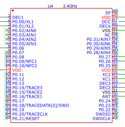
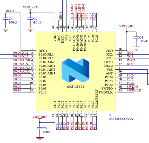
    You mention that you are using the nRF52840, but the SoC used in the schematic does not match up with any of the versions of the nRF52840. Based on the pin numbering  it looks like the nRF52832 have been used:

    There are differences in the required external components between the nRF52840 and the nRF52832 so this part of the schematic must changed  to match the nRF52840 reference schematic. The nRF52840 comes in 3 different packages, which all have different external component requirements.

    - Are my power nets designed the right way ?

    The aQFN73 and the WLCSP versions of the nRF52840 can be used in high voltage mode which accepts a input voltage range of 5.5V to 2.5V. This means that you can remove the NCP114 and supply the nRF52840 directly from the battery.

    USB -> UART: The CP2104 is used to program the NRF52840 by an USB cable.
    - Maybe my biggest question of this whole project. This PCB is eventually going to be mass produced after the prototypes are tested and fully working. What is the best way to program a board like this when its going to be mass produced. I saw somebody do it this way and i liked it because it uses the USB port. But i also saw that they use the SWDIO and SWDCLK pins but i dont know a lot about this. Can somebody help me with this ?

    To program the device over UART you must first flash a bootloader to the nRF52840,  for this you have to use the SWD interface and a external programmer or nRF52840DK. So the SWDIO and SWDCLK pins must be available to connect the programmer.

    - Is the NRF52840 going to work like this ?

    The current schematic wont work with the nRF52840, i recommend you copy the reference design for the version of  the nRF52840 you are planning on using. You can upload  the updated schematic for me to do a second review.

    - I connected the ANT pin untill the antenna itself. I need to look further into this which antenna is good for this project but maybe somebody can already help me with this ?

    There is multiple types of antennas you can use,  the main categories are PCB and chip  antennas. PCB antennas are very cheap, as the are made from PCB traces. Chip antennas are easy to use, as you just need to copy the antenna footprint from the antenna datasheet. Both types of antennas needs to be tuned,  which is something we can help with, if you don't have the equipment to do  it yourself.

    We have a paper on designing a monopole PCB antenna,  available here:  https://infocenter.nordicsemi.com/pdf/nwp_008.pdf?cp=18_19

    The design and production files for the nRF52840DK and the nRF52840 dongle are also available for download,  the nRF52840DK  uses a monopole PCB antenna, while the nRF52840 dongle uses a meandering PCB antenna.
    https://www.nordicsemi.com/Products/Development-hardware/nRF52840-Dongle/Download?lang=en#infotabs

    https://www.nordicsemi.com/Products/Development-hardware/nRF52840-DK/Download#infotabs


    Best regards,

    Bendik

Reply
  • Hi again Léon,

    No problem, most customers want the design files to be private, so I made it private just in case it was mistakenly made public.

    You mention that you are using the nRF52840, but the SoC used in the schematic does not match up with any of the versions of the nRF52840. Based on the pin numbering  it looks like the nRF52832 have been used:

    There are differences in the required external components between the nRF52840 and the nRF52832 so this part of the schematic must changed  to match the nRF52840 reference schematic. The nRF52840 comes in 3 different packages, which all have different external component requirements.

    - Are my power nets designed the right way ?

    The aQFN73 and the WLCSP versions of the nRF52840 can be used in high voltage mode which accepts a input voltage range of 5.5V to 2.5V. This means that you can remove the NCP114 and supply the nRF52840 directly from the battery.

    USB -> UART: The CP2104 is used to program the NRF52840 by an USB cable.
    - Maybe my biggest question of this whole project. This PCB is eventually going to be mass produced after the prototypes are tested and fully working. What is the best way to program a board like this when its going to be mass produced. I saw somebody do it this way and i liked it because it uses the USB port. But i also saw that they use the SWDIO and SWDCLK pins but i dont know a lot about this. Can somebody help me with this ?

    To program the device over UART you must first flash a bootloader to the nRF52840,  for this you have to use the SWD interface and a external programmer or nRF52840DK. So the SWDIO and SWDCLK pins must be available to connect the programmer.

    - Is the NRF52840 going to work like this ?

    The current schematic wont work with the nRF52840, i recommend you copy the reference design for the version of  the nRF52840 you are planning on using. You can upload  the updated schematic for me to do a second review.

    - I connected the ANT pin untill the antenna itself. I need to look further into this which antenna is good for this project but maybe somebody can already help me with this ?

    There is multiple types of antennas you can use,  the main categories are PCB and chip  antennas. PCB antennas are very cheap, as the are made from PCB traces. Chip antennas are easy to use, as you just need to copy the antenna footprint from the antenna datasheet. Both types of antennas needs to be tuned,  which is something we can help with, if you don't have the equipment to do  it yourself.

    We have a paper on designing a monopole PCB antenna,  available here:  https://infocenter.nordicsemi.com/pdf/nwp_008.pdf?cp=18_19

    The design and production files for the nRF52840DK and the nRF52840 dongle are also available for download,  the nRF52840DK  uses a monopole PCB antenna, while the nRF52840 dongle uses a meandering PCB antenna.
    https://www.nordicsemi.com/Products/Development-hardware/nRF52840-Dongle/Download?lang=en#infotabs

    https://www.nordicsemi.com/Products/Development-hardware/nRF52840-DK/Download#infotabs


    Best regards,

    Bendik

Children
  • Thank you Bendik for your review! I am wondering, isn't it easier for me to just choose the NRF52832 for my project ? LCSC (the component supplier of EASYEDA) has an package of this one available with solder pads on the side instead of the NRF52840 which has it on the underside of the chip. I am planning to solder the first couple of prototypes myself untill i am sure everything works as it should. If i choose for the NRF52832, is my circuitry right and i need to keep the NCP114 right ?

  • It depends on what features you need, the nRF52832 is lacking some of the features of the nRF52840 and it also has less RAM and flash. Here is a list comparing all the nRF52 series devices with each other to help with deciding which device is best for your application:
    https://infocenter.nordicsemi.com/topic/struct_nrf52/struct/nrf52.html?cp=5

    One feature you might want is the built in USB peripheral in the  nRF52840, with this you can get rid of the USB to UART bridge.

    LJBouman said:
    LCSC (the component supplier of EASYEDA) has an package of this one available with solder pads on the side instead of the NRF52840 which has it on the underside of the chip. I am planning to solder the first couple of prototypes myself untill i am sure everything works as it should.

    There is a version of the nRF52840 in a QFN package, nRF52840-QFAA, which is the same package as the nRF52832. This version of the nRF52840 is missing some of the features the other packages have, mainly the high voltage regulator  and the USB peripheral.

    When you are soldering the chip yourself you have to keep in mind that the center GND pad under the SoC needs a good solder connection to the board. This is important for the radio to function properly.

    LJBouman said:
    If i choose for the NRF52832, is my circuitry right and i need to keep the NCP114 right ?

    Yes, the nRF52832 have a maximum input voltage of 3.6V, keeping the regulator will insure that the supply voltage is within the specifications.

  • Hi Bendik, again thank you for your usefull answer. I decided to replace the NRF52840 for the NRF52832. It still fits my needs and it might be easier for me. Maybe in the future i can always update to the NRF52840. I updated my schematic (Sheet 1 V2) and have added it in my comment. I also removed the CP2104 and added a header to SWDIO and SWDCLK. I am planning to program my board throug a NRF development board. I still haven't add an antenna but maybe you can review my schematic again ? Sheet 1 V2.pdf

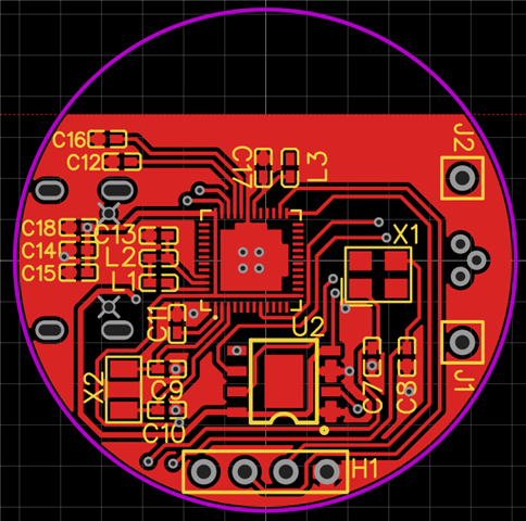
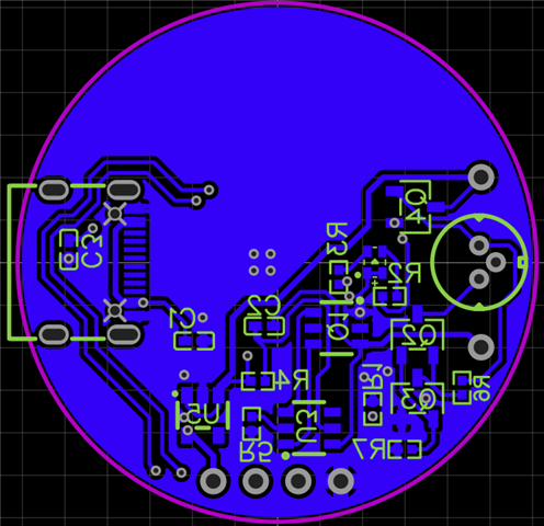
  • Hi Bendik, in the mean time i designed the first version of the PCB itself. I tried to do as much research as possible and process it in the design. If you can review the PCB as well that would be great!
      

  • Comment: The upper section of the PCB is for the antenna

Related