Hardware setup: Custom board using BC805M-P (with App protect)
Software: nrf5 SDK S112 v17.0.2 ->Segger V7.30
My Objective:
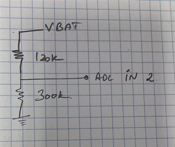
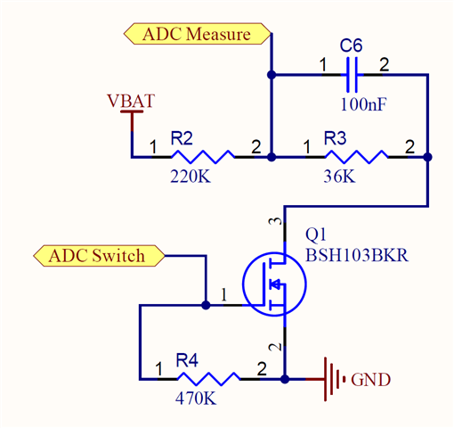
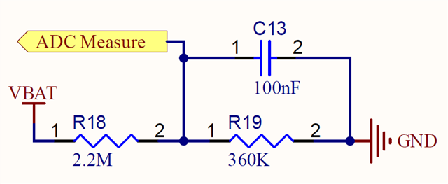
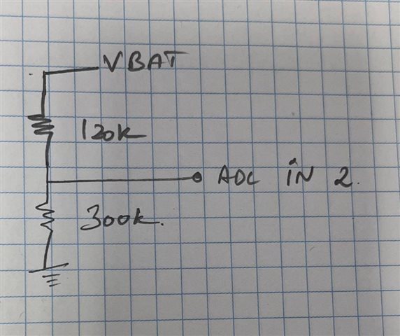
measure the Li-ion battery voltage(4.2V -100% till 3.6V-0%) through an external resistive divider & internal 0.6v ref voltage. (I'm not worried about the current consumption as of this moment. would like to make this concept work & all the other optimisations shall see later. Regarding optimisations yes I'm aware of this page: https://devzone.nordicsemi.com/nordic/nordic-blog/b/blog/posts/measuring-lithium-battery-voltage-with-nrf52)
What works so far?
for the moment my example measured voltage value is being transmitted over BLE through the battery service. it's all working well.
But the ADC is just measuring some garbage value (random) which is clearly not correct.
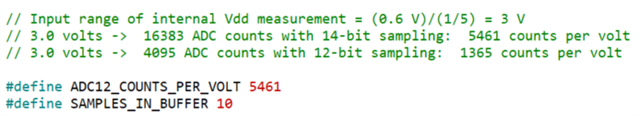
My concept of ADC polling mode is taken from this post & modified for my work. https://devzone.nordicsemi.com/f/nordic-q-a/14486/measuring-the-battery-voltage-with-nrf52832/129422// Input range of External Vdd measurement = (0.6 V)/(1/5) = 3 V
// 3.0 volts -> 16383 ADC counts with 14-bit sampling: 5461 counts per volt
// 3.0 volts -> 4095 ADC counts with 12-bit sampling: 1365 counts per volt
#define ADC12_COUNTS_PER_VOLT 5461
void Adc12bitPolledInitialise(void)
{
uint32_t timeout = 10;
nrf_saadc_channel_config_t myConfig =
{
.resistor_p = NRF_SAADC_RESISTOR_DISABLED,
.resistor_n = NRF_SAADC_RESISTOR_DISABLED,
.gain = NRF_SAADC_GAIN1_5, // (1/5) Gain
.reference = NRF_SAADC_REFERENCE_INTERNAL, // 0.6V internal Ref Voltage
.acq_time = NRF_SAADC_ACQTIME_40US, // See max source resistancetable
.mode = NRF_SAADC_MODE_SINGLE_ENDED,
.burst = NRF_SAADC_BURST_DISABLED,
.pin_p = NRF_SAADC_INPUT_AIN2, // AIN2 for input Pin
.pin_n = NRF_SAADC_INPUT_DISABLED
};
nrf_saadc_resolution_set((nrf_saadc_resolution_t) 3); // 2 is 12-bit , 3 for 14-bit
nrf_saadc_oversample_set((nrf_saadc_oversample_t) 2); // 2 is 4x, about 150uSecs total
nrf_saadc_int_disable(NRF_SAADC_INT_ALL);
nrf_saadc_event_clear(NRF_SAADC_EVENT_END);
nrf_saadc_event_clear(NRF_SAADC_EVENT_STARTED);
nrf_saadc_enable();
NRF_SAADC->CH[1].CONFIG =
((myConfig.resistor_p << SAADC_CH_CONFIG_RESP_Pos) & SAADC_CH_CONFIG_RESP_Msk)
| ((myConfig.resistor_n << SAADC_CH_CONFIG_RESN_Pos) & SAADC_CH_CONFIG_RESN_Msk)
| ((myConfig.gain << SAADC_CH_CONFIG_GAIN_Pos) & SAADC_CH_CONFIG_GAIN_Msk)
| ((myConfig.reference << SAADC_CH_CONFIG_REFSEL_Pos) & SAADC_CH_CONFIG_REFSEL_Msk)
| ((myConfig.acq_time << SAADC_CH_CONFIG_TACQ_Pos) & SAADC_CH_CONFIG_TACQ_Msk)
| ((myConfig.mode << SAADC_CH_CONFIG_MODE_Pos) & SAADC_CH_CONFIG_MODE_Msk)
| ((myConfig.burst << SAADC_CH_CONFIG_BURST_Pos) & SAADC_CH_CONFIG_BURST_Msk);
NRF_SAADC->CH[1].PSELN = myConfig.pin_n;
NRF_SAADC->CH[1].PSELP = myConfig.pin_p;
}
void ble_Update_BatteryVoltage(void)
{
// Enable command & Turn on the Power
nrf_gpio_pin_write(ADC_SWITCH, 1); //turning on the voltage bridge on with a transistor
nrf_saadc_enable();
uint16_t result = 9999; // Some recognisable dummy value
uint32_t timeout = 100000; // Trial and error
volatile int16_t buffer[8];
NRF_SAADC->RESULT.PTR = (uint32_t)buffer;
NRF_SAADC->RESULT.MAXCNT = 1;
nrf_saadc_event_clear(NRF_SAADC_EVENT_END);
nrf_saadc_task_trigger(NRF_SAADC_TASK_START);
nrf_saadc_task_trigger(NRF_SAADC_TASK_SAMPLE);
    if (timeout != 0)
    {
        result = ((buffer[0] * 1000L)+(ADC12_COUNTS_PER_VOLT/
        5)) / ADC12_COUNTS_PER_VOLT;
    }

    while (0 == nrf_saadc_event_check(NRF_SAADC_EVENT_END) && timeout > 0)
    {
        timeout--;
    }
nrf_saadc_task_trigger(NRF_SAADC_TASK_STOP);
nrf_saadc_event_clear(NRF_SAADC_EVENT_STARTED);
nrf_saadc_event_clear(NRF_SAADC_EVENT_END);
// Disable command & turn off the Power to ADC Bridge to reduce power consumption
nrf_saadc_disable();
nrf_gpio_pin_write(ADC_SWITCH, 0); //turning off the voltage bridge on with a transistor
ble_bas_battery_level_update(&m_bas, result, m_conn_handle);
}
The ADC result value is clearly not accurately working when I'm just calling the function manually upon a button press. ble_Update_BatteryVoltage();
What am I doing wrong?
Thanks, for any valuable input I'm new to NRF.
Gokunath