Does anyone have some troubleshooting tips for how to test a custom board with nRF9160.
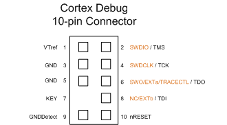
It is a new design, the schematic is based on the DK, including the j-link/swd connector.
We have a 3V3 supply.
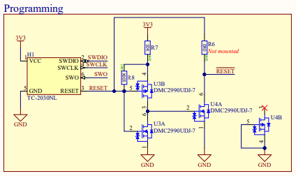
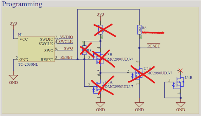
I have been wondering about the inversion of the SWD RESET signal on the DK board so we implemented the schematic with both inversion and direct connection just to be sure. I assume connection of SWD nRESET signal to pin 32 throuth a 1k resistor with a capacitor is how it should be.
Is the a guide on checking the CPU bootup etc...?
I have tested by J-Link on the DK by powering it through the external power connector and using the P18 connector. On the DK my J-Link interface connects.