Issue with I2C communication in with multiple I2C sensors

Hello,

i'm going crazy trying to solve an issue involving I2C communication. I have the following setup: 

- ncs 2.4.2 (can't upload to latest because i have an issue with that...i have an issue open on DevZone)

- NRF5340DK

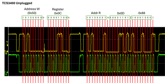
- I2C sensor A (TCS3400)

- I2C sensor B (MCP9808)

- I2C sensor C (LSM6DSOX)

- I2C sensor D (FDC1004)

I developed all the libraries to communicate with these sensors (yes, i know that many of them are supported by Zephyr but drivers were lacking many features such as interrupt, etc.). All the libraries have been tested arranging the breakouts of the sensors on a breadboard.

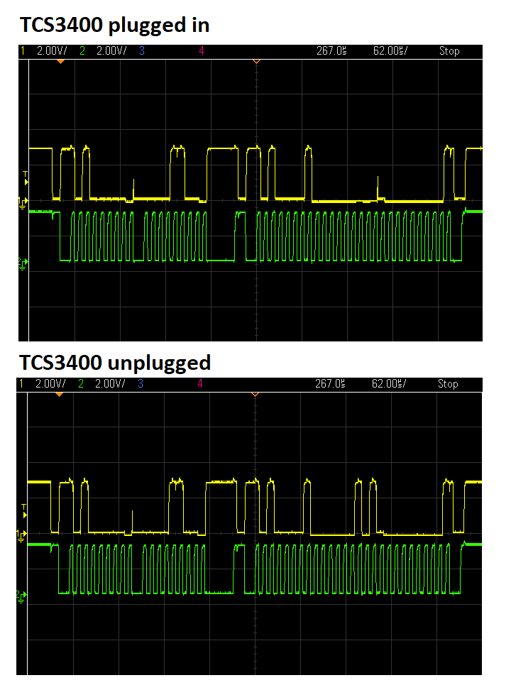
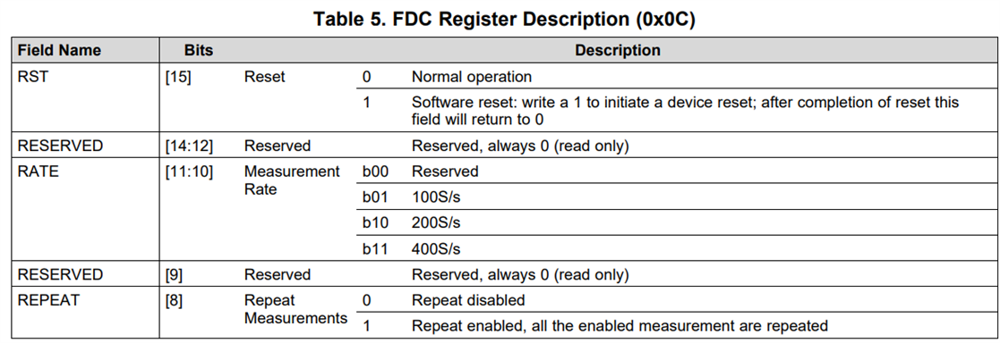
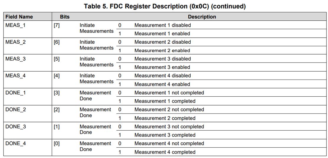
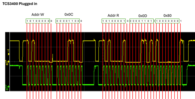
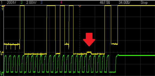
Now, this is the problem: when i try to read data from the FDC1004 (using the required sequence of commands: trigger measure -> check if measure is done -> read measure) AND the sensor A is connected, the "MEASURE_DONE" bit is NEVER set. Please note that the I2C function that reads the register is working (i can read the register content and all the other bits are correctly set). If i unplug the SDA or SCL or VDD for the breakout of sensor A the MEAS_DONE bit is instantly set.

Please note that:

- Connecting or disconnecting sensor B and C is totally irrelevant. If they are connected they work fine, if they are disconnected i still have the exact same problem with A and D. This exclude any problem about the loading of the SDA/SCL paths. Moreover, as i said, ALL the functions with ALL the sensors are working, with the exception of the function "isMeasDone()";

- The only function with this strange behaviour is "isMeasDone()". All the other functions set and read all the correct values in all the registers of every sensor;

- Each sensor by itself works with the code i wrote. This means that there are no issues with the addresses and the write/read functions;

- Sensors do not have the same I2C address. I double-checked it and, moreover, i highlight again that i have this issue ONLY with that specific function;

- The TCS3400 breakout is the only one without pull-up resistors for SDA and SCL on the board, but because of the fact that the other sensor breakouts have it, this is not needed. I measured the overall pull-up values (the parallel of all the pull-up of the several breakouts) is 5.2k, so this should be fine;

- Logging is active in the project. This allows me to track any error on the comunication...and there is not.

Unfortunately i cannot share the project because it has tens of source files and would be very unpractical. Here below you can find the definition of the of the function that is giving me trouble. Again, this function works perfectly if sensor A is not connected, so there should be no issue with the code....however...here you go:

Just for the sake of completeness, here below is the section of code that is generating my headache:

I'm not able to get out of this on my own. I am not even able to understand if this is an hardware or a software issue. I hope your experience can provide me some hints to solve it.

Thank you,
Frax

  • Yes, without the SCL to mark the bits it's hard to decode; assuming only Meas 1 is enabled and complete there should be a '1' for only meas 1 and not 2, 3 and 4 but I'm not seeing that in the traces above (al least not without SCL as a guide). Does the 'scope have an I2C decode function? That would obviously help.

    With the TCS3400 in place, does shorting the capacitive sense CIN or guard SHLD pin to Gnd have the same adverse effect as removing the TSC3400? Maybe something is stopping the measure clock which in turn defeats the completion of measurement.

  • Dear  ,  

    here below you can find what you asked. Unfortunately my scope has not I2C decode function Disappointed

    There is something i'm not convinced on watching these plots. I had no time to review them carefully so i'm taking tomorrow for that, but if you compare these plots with the previous ones you will notice a significant difference between the "TCS3400 plugged in" case of yesterday and today for one bit. They have been taken in identical conditions, so i expect them to be identical. I need to investigate it.

    The plots refer to a I2C read request (isMeasDone() function) to the register FDC_CONF (address 0x0C) of the FDC1004 device (I2C address 0x50). The register is structured as follows:

    The configuration of this register just before the "isMeasDone()" function is: 100Sample/s, Repeat Meas enabled,  MEAS_1 Initiate measurement enabled. 

    Another thing i want to try tomorrow is to power down the TCS3400 while measuring with FDC1004. Cannot test it right now because i didn't write the function to power down TCS3400. It would be a workaround and not a solution, but it could provide some useful info.

    Last but not least, i got another FDC1004 chip and i want to try to use that one to see if anything changes. Low chances, but it comes for free.

    I'll keep you updated!

    Very thanks for the continous support,

    Frax

  • This is my quick decoding:

    0x0000: Measurement Rate Invalid, Repeat disabled, all measurements disabled

    0x0500: Measurement Rate 400S/s, Repeat disabled, all measurements disabled

  • Yes, something is off. I need to dedicate a significative time slot for that. I'll update you within a couple of days this time, so that I'm sure to put here some relevant experiment data

  • Here i am with new developments,

    At first, i understood why the I2C packets were messed up. This was my fault when, trying to fix my issue, i used a function "fdc1004_reset()" to reset the device just before setting up the acquisition parameters. Because i didn't wait for the device to fully reset, the device was not ready to set the acquisition parameters. After this fix, this is what i obtain from I2C analysis when i run the "isMeasDone()"  function:

    Everything is how it should be, with the exception of the "guilty" bit in the last byte, that should be 0x88 and not 0x80.

    When the TCS3400 is unplugged the situation changes:

    In this case everything is how it should be.

    Things i tried/discovered:

    - I tried to powerDown the TCS3400 during I2C transactions with FDC1004. Nothing changed.

    - I tried another FDC1004 chip. Nothing changes. Unfortunately, i have not another TCS3400 to test the same with the other sensor;

    - I studied the TCS3400 breakout and i discovered that there is an I2C EEPROM together with the TCS3400 sensor. Based on the breakout schematic that i found out on the AMS website, the EEPROM I2C address is 0xA0, so it should not create issues.

    - I noticed something that i want to remark, even if it could just be me being insanely suspicious. If you  zoom in the "TCS3400 plugged in" plot on the part where the "1" bit is missing, this is what you see

    In the very same spot where the bit should be "1", there is a very small bump (about 30-40 mV), exacty 1-clock cycle wide. I have no idea why it is like this and if it can be any relevant, but it's exactly where the "1" should be.

    Share your thoughts with me Slight smile

    Thank you

    Frax

« 2 3 4 5 6