Device tree setting problem

Hi 

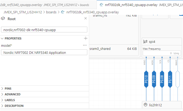
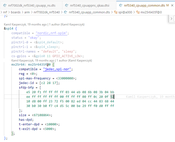
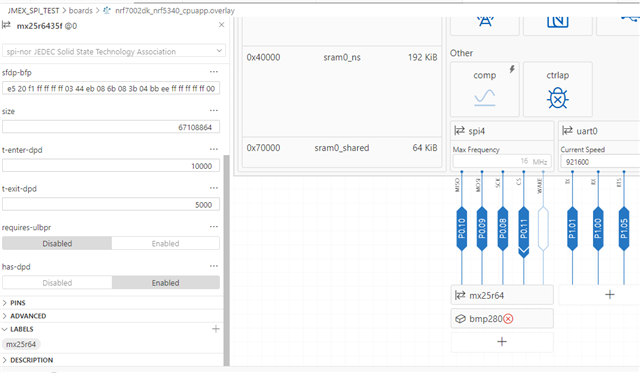
  Iam use nRF7002-DK, SDK v2.5.2, I try to set high seed SPI as master and connect with BMP280 sensor,I generate overay file for spi4 connect BMP280 sensor,for this resource in nrf5340_cpuapp_common.dts connect mx25r64 NOR flash first, as below picture, can I coonect two resource on this SPI4 or remove this NOR flash to other SPI resouce?If connect two on same SPI or remove the NOR falsh to other SPI resource, what the side effect happen for change setting? 

Best Regards

      Tina

  • Hi Simonr

                  For this log,I really to write value to register as below.but when write to registers no any error message for write fail info.sometime registers value is "Zero" when I was solid connection the board and sensor.

    Define register

    #define CTRL3       0x22
    #define CTRL4       0x23
    #define CTRL5       0x24
    #define CTRL6       0x25
    #define CTRL7       0x26

    Write function

    static int lis_write_reg(uint8_t reg, uint8_t value)
    {
    int err;

    /* STEP 5.1 - declare a tx buffer having register address and data */
    uint8_t tx_buf[] = {(reg & 0x7F), value};
    struct spi_buf tx_spi_buf = {.buf = tx_buf, .len = sizeof(tx_buf)};
    struct spi_buf_set tx_spi_buf_set = {.buffers = &tx_spi_buf, .count = 1};
    /* STEP 5.2 - call the spi_write_dt function with SPISPEC to write buffers */
    err = spi_write_dt(&spispec, &tx_spi_buf_set);
    if (err < 0) {
    LOG_ERR("spi_write_dt() failed, err %d", err);
    return err;
    }
    LOG_ERR("spi_write_dt() SUCCESS, err %d", err);
    return 0;
    }

    In main

    {

        lis_write_reg(CTRL3, 0x9F);
        lis_write_reg(CTRL4, 0x9F);
        lis_write_reg(CTRL7, 0x9F);
    }
    Log for solid connection the board and sensor
    *** Booting nRF Connect SDK v2.5.2 ***
    [00:00:00.250,366] <inf> Lesson5_Exercise1: -------------------------------------------------------------
    [00:00:00.250,366] <inf> Lesson5_Exercise1: lis_read_calibrationdata: Reading from calibration registers:
    [00:00:00.250,396] <inf> Lesson5_Exercise1: Reg[0x0b] 2 Bytes read: Param T1 = 0
    [00:00:00.300,842] <inf> Lesson5_Exercise1: Reg[0x0f] = 0x00
    [00:00:00.321,044] <inf> Lesson5_Exercise1: Reg[0x1e] = 0x00
    [00:00:00.341,217] <inf> Lesson5_Exercise1: Reg[0x1f] = 0x00
    [00:00:00.361,389] <inf> Lesson5_Exercise1: Reg[0x20] = 0x00
    [00:00:00.381,591] <inf> Lesson5_Exercise1: Reg[0x21] = 0x00
    [00:00:00.401,763] <inf> Lesson5_Exercise1: Reg[0x22] = 0x00
    [00:00:00.421,936] <inf> Lesson5_Exercise1: Reg[0x23] = 0x00
    [00:00:00.442,108] <inf> Lesson5_Exercise1: Reg[0x24] = 0x00
    [00:00:00.462,310] <inf> Lesson5_Exercise1: Reg[0x25] = 0x00
    [00:00:00.482,482] <inf> Lesson5_Exercise1: Reg[0x26] = 0x00
    [00:00:00.502,655] <inf> Lesson5_Exercise1: Reg[0x27] = 0x00
    [00:00:00.522,827] <inf> Lesson5_Exercise1: Reg[0x28] = 0x00
    [00:00:00.543,029] <inf> Lesson5_Exercise1: Reg[0x26] = 0x00
    [00:00:00.563,201] <inf> Lesson5_Exercise1: Reg[0x27] = 0x00
    [00:00:00.583,404] <inf> Lesson5_Exercise1: Reg[0x28] = 0x00
    [00:00:00.603,546] <inf> Lesson5_Exercise1: Reg[0x29] = 0x00
    [00:00:00.623,748] <inf> Lesson5_Exercise1: Reg[0x2a] = 0x00
    [00:00:00.643,920] <inf> Lesson5_Exercise1: Reg[0x2b] = 0x00
    [00:00:00.664,093] <inf> Lesson5_Exercise1: Reg[0x2c] = 0x00
    [00:00:00.684,265] <inf> Lesson5_Exercise1: Reg[0x2d] = 0x00
    [00:00:00.704,467] <inf> Lesson5_Exercise1: Reg[0x2e] = 0x00
    [00:00:00.724,548] <inf> Lesson5_Exercise1: -------------------------------------------------------------
    [00:00:00.724,578] <inf> Lesson5_Exercise1: Continuously read sensor samples, compensate, and display
    [00:00:00.724,639] <inf> Lesson5_Exercise1: uncomp = 0 C
    [00:00:01.724,761] <inf> Lesson5_Exercise1: uncomp = 0 C
    [00:00:02.724,884] <inf> Lesson5_Exercise1: uncomp = 0 C
    [00:00:03.725,097] <inf> Lesson5_Exercise1: uncomp = 0 C
    Best Regards
          Tina
  • Hi

    How have you added the SPI pins you're using in your overlay file? You should use pins (P0.08-P0.12) to take advantage of the SPIM4 instance, and that needs to be reflected in your overlay file as explained in steps 2.1 and 2.2 of the Academy course you're referring to. Also, please show me a picture of how you have connected the BMP sensor to your nRF7002DK exactly, as something isn't set up correctly if you're not able to write the addresses correctly.

    Best regards,

    Simon

  • Hi Simonr

                    Attached file is for my overlay file, and chip visual picture, Thanks.

    2570.nrf7002dk_nrf5340_cpuapp.overlay

    Best Regards

        Tina

  • Hi

    I see you've set the SPI max frequency to 8MHz here, wasn't the point to have the SPI4 at a higher frequency than the standard SPI speed? That being said I don't see a specific issue with this overlay file. For the picture I meant a photo of the physical connection so I could make sure it looks like it's connected correctly.

    Best regards,

    Simon

  • Hi Simonr

                 wasn't the point to have the SPI4 at a higher frequency than the standard SPI speed?

    Now is testing with ST:LIS2HH12 sensor connection and transmit/recieve , for this sensor the max frequency is 8MHz, but we will try to use high speed with other device connection in future, so need to testing spi4 with low frequency temporary. 

    For the picture I meant a photo of the physical connection so I could make sure it looks like it's connected correctly.

    Connection is correct, but the pin function is not work correctly.For P0.08(SCK) no any waveforms when the activity is start, but the (CS)P0.11 has waveforms by use oscilloscope and logic analyzer.So the result of read/write byte for sensor is no any values as upper, What configuration or detail did I miss for this case?    

    Best Regards

         Tina

Related