Review PCB design for nrf52840 for Matter or Thread use

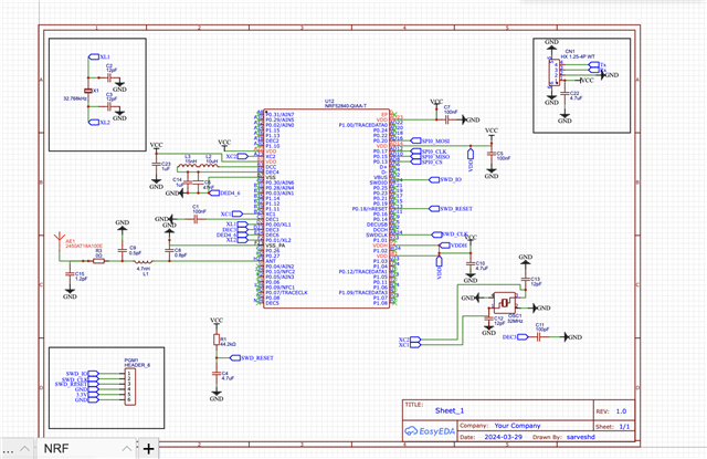
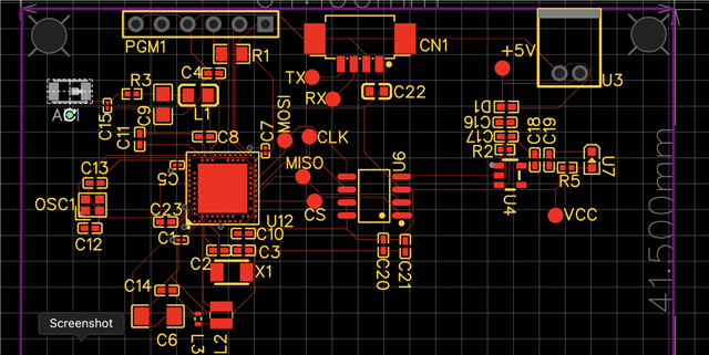
Hi, I am new to PCB design, so I want suggestions for my designed PCB. Please review it once and provide feedback upon that. I am making this PCB to use this with Thread and matter-related products. I have used EasyEda to design the PCB and used the reference designs provided by Nordic. 

 nRF52840 PCB & Antenna Design 

 General PCB design guidelines for nRF52 series 
Parents
  • Hi,

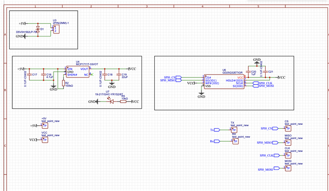
    1. On the SWD header you want to route out VCC not 3V3, so that it follows whatever voltage VCC is at. 
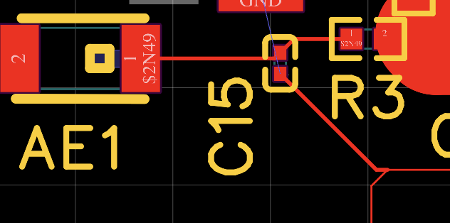
    2. You need a full Pi-network to tune your antenna. Only C15 is not enough. 
    3. DEC4_DEC6 node is connected to the wrong node. It should be over capacitors of the DC/DC components.
    4. You need decoupling on pin A22.
    5. Pullup on Reset pin is not necessary.
    6. What is the internal capacitance of your HFXO and LFXO crystals?

    For the PCB you need to follow the reference design much more closely. Where is your GND layer?

    regards

    Jared 

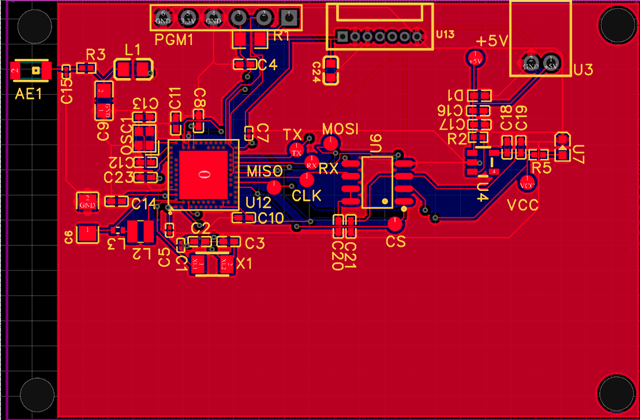
  • Hi, Thanks for the response, I have updated the design with the Gnd. I will update here after changing the other points you have mentioned . Would you please look into this once and find any improvements


  • Hi,

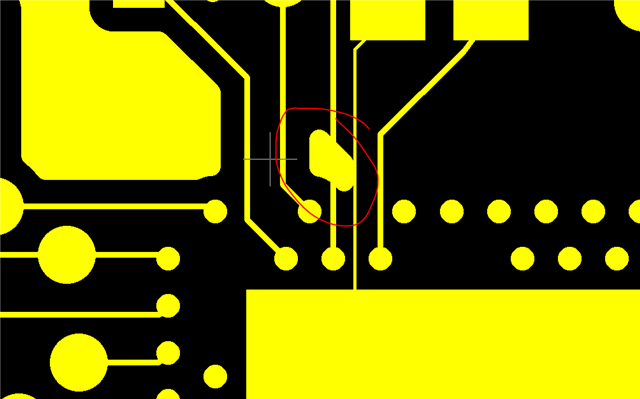
    1. What is this:
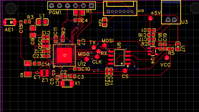
    2. The matching components for the radio needs to be placed much more closer to the radio.

    3. It seems that you changed the ANT path, can you share the schematic for the new revision as well?
    4. Did you place the matching network for the chip antenna? You need a full PI. They should be placed very close to the antenna. 

    5. What is the trace width that you're using?

    regards

    Jared 

  • The matching components for the radio needs to be placed much more closer to the radio.

    How close are you saying they should be?

    It seems that you changed the ANT path, can you share the schematic for the new revision as well?

    No, I have not changed the ANT path, I have added a connector also via Resistor to use the external antenna or onboard antenna options

    What is the trace width that you're using?

    All the traces are 0.051 mm in width, and ANT traces is 2.92 mm

    Did you place the matching network for the chip antenna? You need a full PI. They should be placed very close to the antenna. 

    Yes, there is an RC filter for that as well .

  • Hi,

    You need at full Pi network for the tuning the chip antenna, C15 and R3 alone are not enough.

    Regarding the trace width, we recommend 8 mils = 0.2032 mm

    Can you share the datasheet of the antenna?

    Regarding decoupling capacitors, they should be placed as close as possible to the pin that they are decoupling. For example on your design you have placed C5, which is the decoupling for VDD AD14 on the other side of the IC, and then routed the signal on the bottom layer. 

    Also, you should avoid routing anything under the DC/DC components and tracks. It should be solid ground under.

    regards

    Jared 

  • Hi Jared,

    I appreciate your efforts and patience. Thank you for helping me till now. 

    Regarding the trace width, we recommend 8 mils = 0.2032 mm

    But if I set all the lines coming out for the CHIP to this width the causes the DRC error. so can I fan out the pins from the IC, then after that all the connections it will make with 0.2032 mm width?

    Here is the datasheet for Antenna  - Part no - 2450AT18A100E

    www.johansontechnology.com/.../2450AT18A100.pdf

  • Hi,

    I think that you get DRC error because you have set the track clearance too high. 

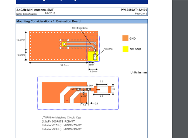
    The datasheet for the antenna specifies that antenna should be placed at the corner of the board, and that minimum a T network is required for tuning:

    regards

    Jared 

Reply Children
Related