
Hello,
I want to set the transmitting power of the advertising packet. How can I set the TX power?
I am using nRF Connect SDK 2.5.1 in Visual Studio Code.
Regards,
Sri
Hello,
I want to set the transmitting power of the advertising packet. How can I set the TX power?
I am using nRF Connect SDK 2.5.1 in Visual Studio Code.
Regards,
Sri

Hi
You can change the TX power with the following Kconfigs CONFIG_BT_CTLR_TX_PWR_xx or CONFIG_BT_CTLR_TX_PWR_ANTENNA.
Regards
Runar
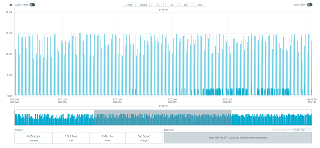
Hi, I have used the CONFIG_BT_CTLR_TX_PWR_xx for power setting. I have done a current consumption test to confirm the change in output power. I found a peculiar result for negative power settings, there are multiple current consumption peaks. For each advertisement taking different current.
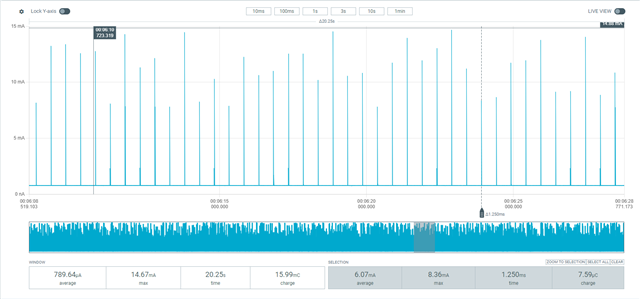
My Observations:
| Tx Power | Tx - Peak | Tx - Avg | Idle | |||
| 8dBm | 28.62mA | 15.65mA | 776uA | |||
| 4dBm | 19.59mA | 12.38mA | 774uA | |||
| 0dBm | 13.71mA | 8.2mA | 774uA | |||
| -4dBm | 14.61mA | 6.91mA | 774uA | 8.48mA | 6.55mA | Multiple amplitude peaks - unknown reason |
| -8dBm | 14.47mA | 6.53mA | 774uA | 8.36mA | 6mA | Multiple amplitude peaks - unknown reason |
| -12dBm |
Skipped
|
|||||
| -16dBm | ||||||
| -20dBm | 14.75mA | 5.48mA | 774uA | 9.31mA | 4.92mA | Multiple amplitude peaks - unknown reason |
So is this the expected behavior or is there a issue?
I want to reduce my Tx Current consumption. I read that if I enable DC/DC it will reduce the current. How do I enable it?
I also want to put my device to sleep after stopping advertisement and in between advertisement to save power. How do it do that?
TIA
Sri
I have custom board. So cant follow the setup from the reference but followed the setup given in PPK user guide. I want to change the Power from LDO to DCDC mode. Can you help me with that? How should I configure the code?
I am using the below code from nRF Academy
/*
 * Copyright (c) 2023 Nordic Semiconductor ASA
 *
 * SPDX-License-Identifier: LicenseRef-Nordic-5-Clause
 */

#include <zephyr/kernel.h>
#include <zephyr/logging/log.h>
/* STEP 3 - Include the header file of the Bluetooth LE stack */
#include <zephyr/bluetooth/bluetooth.h>
#include <zephyr/bluetooth/gap.h>

#include <dk_buttons_and_leds.h>

LOG_MODULE_REGISTER(Lesson2_Exercise1, LOG_LEVEL_INF);

#define DEVICE_NAME CONFIG_BT_DEVICE_NAME
#define DEVICE_NAME_LEN (sizeof(DEVICE_NAME) - 1)

#define RUN_STATUS_LED DK_LED1
#define RUN_LED_BLINK_INTERVAL 1000

/* STEP 4.1.1 - Declare the advertising packet */
static const struct bt_data ad[] = {
	/* STEP 4.1.2 - Set the advertising flags */
	BT_DATA_BYTES(BT_DATA_FLAGS, BT_LE_AD_NO_BREDR),
	/* STEP 4.1.3 - Set the advertising packet data  */
	BT_DATA(BT_DATA_NAME_COMPLETE, DEVICE_NAME, DEVICE_NAME_LEN),

};

/* STEP 4.2.2 - Declare the URL data to include in the scan response */
static unsigned char url_data[] = { 0x17, '/', '/', 'a', 'c', 'a', 'd', 'e', 'm',
				    'y',  '.', 'n', 'o', 'r', 'd', 'i', 'c', 's',
				    'e',  'm', 'i', '.', 'c', 'o', 'm' };

/* STEP 4.2.1 - Declare the scan response packet */
static const struct bt_data sd[] = {
	/* 4.2.3 Include the URL data in the scan response packet */
	BT_DATA(BT_DATA_URI, url_data, sizeof(url_data)),
};

int main(void)
{
	int blink_status = 0;
	int err;

	LOG_INF("Starting Lesson 2 - Exercise 1 \n");

	err = dk_leds_init();
	if (err) {
		LOG_ERR("LEDs init failed (err %d)\n", err);
		return -1;
	}
	/* STEP 5 - Enable the Bluetooth LE stack */
	err = bt_enable(NULL);
	if (err) {
		LOG_ERR("Bluetooth init failed (err %d)\n", err);
		return -1;
	}

	LOG_INF("Bluetooth initialized\n");

	/* STEP 6 - Start advertising */
	err = bt_le_adv_start(BT_LE_ADV_NCONN, ad, ARRAY_SIZE(ad), sd, ARRAY_SIZE(sd));
	if (err) {
		LOG_ERR("Advertising failed to start (err %d)\n", err);
		return -1;
	}

	LOG_INF("Advertising successfully started\n");

	for (;;) {
		dk_set_led(RUN_STATUS_LED, (++blink_status) % 2);
		k_sleep(K_MSEC(RUN_LED_BLINK_INTERVAL));
	}
}
How can I put my nRF52833 in "ION_RAMOFF_EVENT" or "ION_RAMOFF_RTC". I need it to sleep for 5 mins and wake up
Using the DCDC should be as easy as using the Kconfig option CONFIG_SOC_DCDC_NRF52X=y
What is the usecase for your application? I would recommend reading Einars reply https://devzone.nordicsemi.com/f/nordic-q-a/99280/sleep-modes-system-on-example-for-nrf52833-with-nrf-connect-sdk-2-3-0?ReplySortBy=CreatedDate&ReplySortOrder=Ascending regarding power modes
Regards
Runar
Use case is to make a BLE beacon.
If I add CONFIG_SOC_DCDC_NRF52X=y in the kconfig file then it is saying
error: SOC_DCDC_NRF52X (defined at soc/arm/nordic_nrf\nrf52\Kconfig.soc:85) is assigned in a
configuration file, but is not directly user-configurable (has no prompt). It gets its value
indirectly from other symbols. See
http://docs.zephyrproject.org/latest/kconfig.html#CONFIG_SOC_DCDC_NRF52X and/or look up
SOC_DCDC_NRF52X in the menuconfig/guiconfig interface. The Application Development Primer, Setting
Configuration Values, and Kconfig - Tips and Best Practices sections of the manual might be helpful
too.
So any other way to enable the DCDC mode?
if I add "CONFIG_BOARD_ENABLE_DCDC=y" to the proj.cofig it is showing below error:
warning: attempt to assign the value 'y' to the undefined symbol BOARD_ENABLE_DCDC
I have created a new board in NRF Connect for the board I am using. Do I need to do anything different because it has a different device tree file?
Regarding the power modes I want to measure current consumption in "ION_RAMON_RTC", "ION_RAMOFF_RTC", "ION_RAMOFF_EVENT". Since my application is beacon I don't need to remember anything so I can turn off the RAM. I want to try all the three modes. Can you suggest a reference code to put the device in the before mentioned states?
Could you share your board files so that I can have a look at them?
Did you do as in step 6 here? If not, try to do it and see if it works
I will need to check regarding ION_RAM_OFF and so on as I have never seen it used. But you could also check out https://docs.nordicsemi.com/bundle/ncs-latest/page/nrf/libraries/others/ram_pwrdn.html
Regards
Runar
I have completed the steps told in the document. But still getting multiple current peaks for each advertisement. The power setting in proj.conf is CONFIG_BT_CTLR_TX_PWR_0=y
The expected current consumption is 10.3 mA in normal mode and 4.9mA in DC/DC mode. So anything I am missing? I followed all the steps in the document you shared to create a custom board.
Thank you for sharing the documentation. I have followed it and now in idle it is consuming 1.3 - 1.5uA (Avg). I turned off the serial and other unused peripherals.
![]()
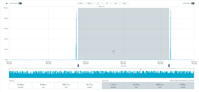
The transmission power is still not matching the values given in the datasheet. It is varying. How do i get the 5mA specified in the datasheet?
TIA
Sri
