Getting Error while connecting nRF9160DK module to nRF7002DK module with spi and use it for wifi locationing

Dear Nordic Team,

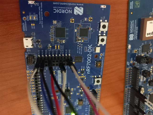
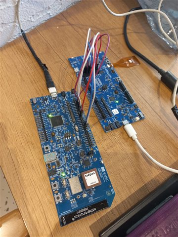
I want to connect my nRF9160DK board to my nRF7002DK board and get a wi-fi location. I've followed samples/cellular/nrf_cloud_multi_service as sample and I made wiring as follows

Board nRF9160-DK(P3 & P4) nRF7002-DK (P24)
SPI CLK P0.13 P0.17
SPI CS P0.10 P0.18
SPI MOSI P0.11 P0.13
SPI MISO P0.12 P0.14
HOST-IRQ  P0.07 P0.23
IOVDD-CTR  P0.00 P0.31
BUCKEN P0.01 P0.12

I soldered SB25 and SB20 on the nRF7002 board.
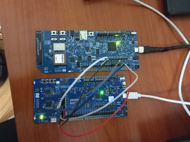
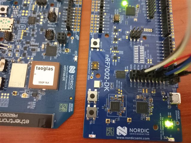


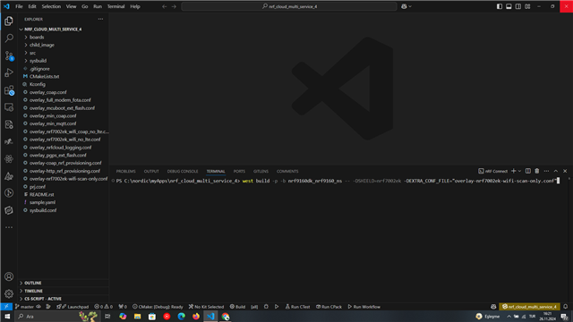
The problem is, whenever I'm trying to build samples/cellular/nrf_cloud_multi_service sample with using overlay-nrf7002ek-wifi-scan-only.conf as Extra Kconfig fragments and -DSHIELD="nrf7002ek" as Extra Cmake arguments.

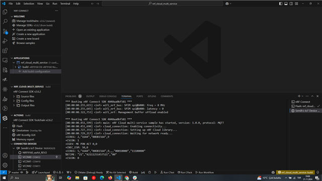
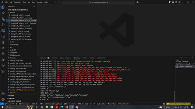
After flashing the sample to the nrf9160DK board, I'm getting the error below:

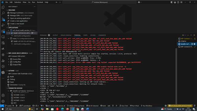
*** Booting nRF Connect SDK 4040aa0bf581 ***
[00:00:00.257,720] <inf> main: nRF Cloud multi-service sample has started, version: 1.0.0, protocol: MQTT
[00:00:00.257,751] <inf> cloud_connection: Enabling connectivity...
[00:00:00.260,284] <inf> wifi_nrf_bus: SPIM spi@b000: freq = 8 MHz
[00:00:00.260,314] <inf> wifi_nrf_bus: SPIM spi@b000: latency = 0
[00:00:00.260,864] <err> wifi_nrf_bus: Error: RPU comms test: sig failed: expected 0x42000020, got 0xffffffff

[00:00:00.260,925] <err> wifi_nrf: zep_shim_bus_qspi_dev_add: RPU enable failed with error -1
[00:00:00.260,986] <err> wifi_nrf: nrf_wifi_bus_qspi_dev_add: nrf_wifi_osal_bus_qspi_dev_add failed
[00:00:00.261,077] <err> wifi_nrf: nrf_wifi_bal_dev_add: Bus dev_add failed
[00:00:00.261,169] <err> wifi_nrf: nrf_wifi_hal_dev_add: nrf_wifi_bal_dev_add failed
[00:00:00.261,322] <err> wifi_nrf: nrf_wifi_fmac_dev_add: nrf_wifi_hal_dev_add failed
[00:00:00.261,383] <err> wifi_nrf: nrf_wifi_fmac_dev_add_zep: nrf_wifi_fmac_dev_add failed
[00:00:00.261,413] <err> wifi_nrf: nrf_wifi_if_start_zep: nrf_wifi_fmac_dev_add_zep failed
[00:00:00.537,200] <inf> cloud_connection: Setting up nRF Cloud library...
[00:00:00.539,093] <inf> cloud_connection: Waiting for network ready...
+CEREG: 2,"1644","00DB1564",9
+CSCON: 1
+CGEV: ME PDN ACT 0,0
+CNEC_ESM: 50,0
+CEREG: 5,"1644","00DB1564",9,,,"00010000","11100000"
%XTIME: "21","42118151436521","00"
+CSCON: 0

Then progress stops completely. The error changes when I disconnect any of the cables, so I thought the problem might be the configuration on the devicetree. and here how it looks like:
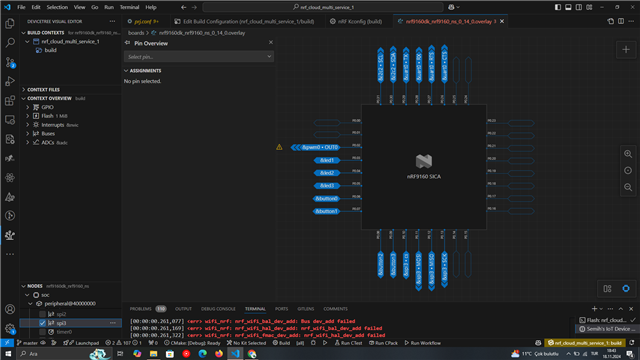

I tried to assign SPI WAKE to P0.07, the HOST-IRQ pin, but this time it started to give this error serially: ASSERTION FAIL @ WEST_TOPDIR/modules/hal/nordic/nrfx/drivers/src/nrfx_gpiote.c:486

I would be very grateful if you can help me solve this error, if there is any extra information that you think may be useful, I will be happy to share it.

Actually what I want to do is to get the wifi location in a simple way and monitor it on nrf cloud with REST protocol. Then I want to add A-GNSS and experience an effective indoor and outdoor location tracking example. I would be glad to hear your extra advice for that too.

Best wishes!

Parents
  • Hi,

    I soldered SB25 and SB20 on the nRF7002 board.

    nRF7002 companion IC documentation specifies that control signal are available on P24 while QSPI is not connected by default. Connection to P24 can be established by shorting solder bridges from SB20 to SB25, not just SB20 and SB25. This is also specified in the nRF7002-dk solder bridge documentation.

    Best regards,
    Dejan

  • Hi Dejans,

    Thanks for your help. I tried again after soldering as you said and I got this output and I think the error is fixed. However, after a while I kept getting the same error again. In this case, can we say that there is a problem with my cables? The only change I made during this process was to try to run the nrf7002 with a powerbank for once. When the LED5 kept blinking, I thought that there was not enough power for the device to work, so I started using the computer again. And even if I power supply from the computer I keep getting the “Error: RPU comms test: sig failed: expected 0x42000020, got 0xffffffffff” error.


    Also, please excuse my inexperience, I have not done any processing or firmware installation since I received the nrf7002dk device. So I started using it as a shield for the nrf9160dk device as it came from the factory.

    In case if I made a mistake to flashed the code to the nrf7002dk instead of nrf9160dk, I thought of cleaning the device with the “erase board” option on the nrf7002dk via VScode and running it again, but this time LED1 and LED2 stopped signaling. I tried to upload the .HEX file again but there was no change.


    Could you please inform me about the points I should pay attention to at this stage? Thank you for your patience and support.

  • Hi,

    Can you show your build command?

    SemihAydin said:
    I tried again after soldering as you said and I got this output and I think the error is fixed. However, after a while I kept getting the same error again. In this case, can we say that there is a problem with my cables? The only change I made during this process was to try to run the nrf7002 with a powerbank for once.

    Can you verify that everything is working as expected if you do not use power bank?

    Best regards,
    Dejan

  • Hi Dejan,

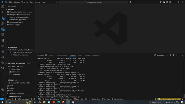
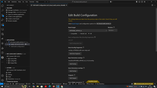
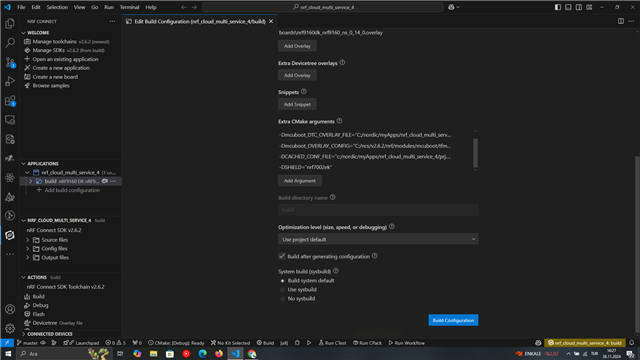
    Sure, I just started from beginning. I've connected my devices to the computer wihout using power bank. I created new sample and build it. Here is my build command and output below,

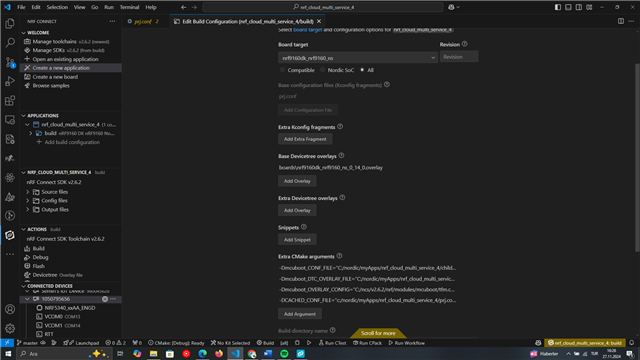
    After I build as above, I checked Edit Build COnfiguration section and here how itt looks like,

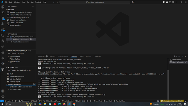
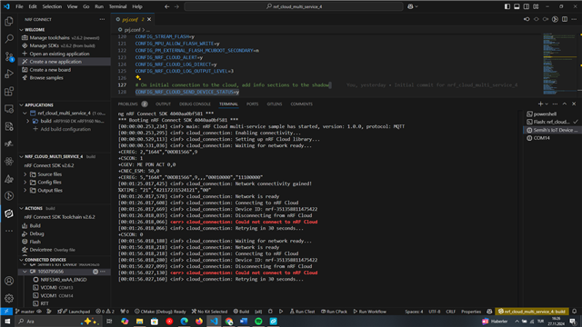
    After that, I flashed to the my nrf9160dk device and I got tthis output in the final,

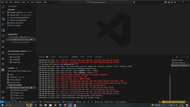
    after waiting for a while, output continued like below and stopped.


    Do we need to check if my nrf7002dk working properly?

    Here's the short summary of my steps,

    1) Before soldering I was getting the following error: “RPU comms test: sig failed: expected 0x42000020, got 0xffffffff”

    2) After soldering, the fault went away.

    3) After soldering I fed it with powerbank for once and the error came back.

    4) After feeding it with Powerbank, I returned to the power supply method from the computer and again I got the error “RPU comms test: sig failed: expected 0x42000020, got 0xffffffff”.

    5) Thinking that there might be a problem with the nRF7002DK board, I first removed the device with the erase board option from the connected devices section on VScode. Until this stage, the LED1 and LED2 lights of my nrf7002dk kit were blinking continuously in sequence. Later, when this disappeared, I opened it with the programmer and printed the “wifi_scan_sample_ncs2.6.0.hex” file in case there might be an error in the device.

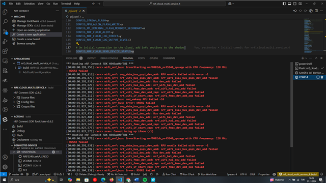
    6) I reinstalled Sample and got the new error.

    I hoppe these infrmation help,

    Best regards,
    Semih.

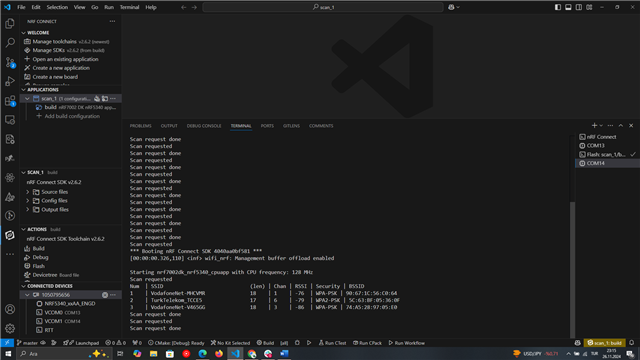
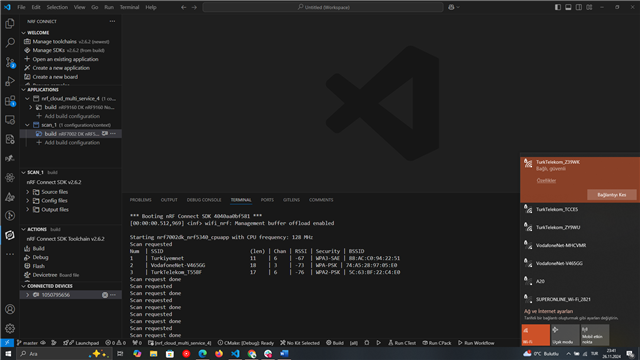
  • In addition, when I build  wifi scan sample with the code "west build -b nrf7002dk_nrf5340_cpuapp" and flashed to my nrf7002dk It scanned and find the wifi's succesfully.


    After that, I decided to connect it to my nrf9160dk again,

    this is the terminal of nrf7002dk(wifi scan sample still flashed inside)

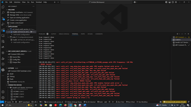
    and this is the terminal of nrf9160dk(multi services sample still flashed inside)


    So, whenever I connected the SPI pins(CLK, CS, MISO, MOSI) this problem occur.

  • Hi Semih,

    Can you show logs from both boards when you build multi service sample on nrf9160-dk without overlay-nrf7002ek-wifi-scan-only.conf and -DSHIELD=nrf7002ek? Do you get the same error?

    Best regards,
    Dejan

  • I builded without overlay-nrf7002ek-wifi-scan-only.conf and -DSHIELD=nrf7002ek


    Here are the results,

    nrf9160dk (LED1-LED2-LED4-LED3 blinking in sequence like square)


    nrf7002dk


Reply Children
No Data
Related