How to properly configure GPIOTE PORT events

Hello,

I am using the following device and development kit:

  • Device: NORA-B106-00B (nRF5340)
  • nRF Connect SDK: 2.0.2

Currently, I am trying to use GPIOTE PORT events to detect interrupts on pins P0.04 and P0.28.

The mask for pins that do not use GPIOTE is defined in the Devicetree as follows:

&gpio0 {
	status = "okay";
	sense-edge-mask = < 0x10000010 >; //Mask GPIOTE events other than P0.04 and P0.28
};

Also, among the pins that mask GPIOTE events are the following pins used as SPIM4.

  • P0.08/SCK
  • P0.09/MOSI
  • P0.10/MISO
  • P0.11/CSN

I have PSRAM connected to SPIM4, which is turned off when idle and turned on when in use.

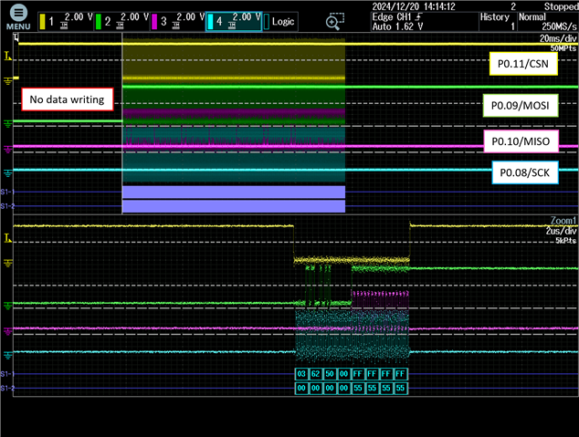
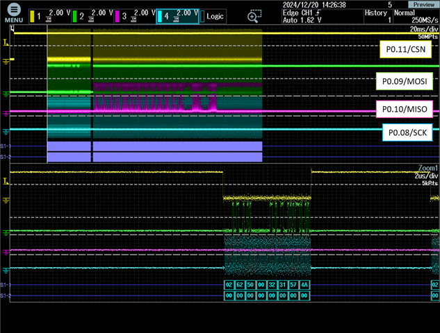
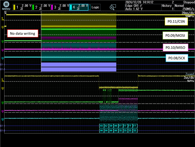
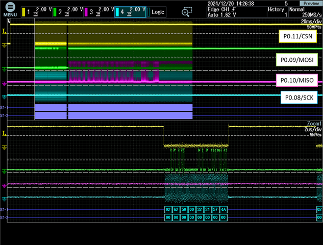
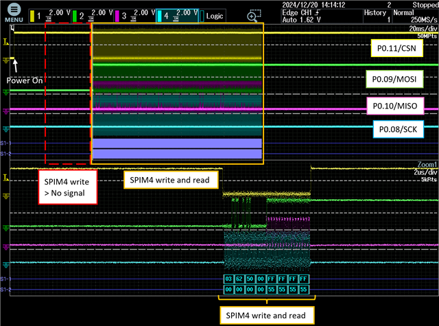
Here, if you try to write data using the nrfx spim driver after the power is turned on (P0.11/CSN:High), the write will not be executed as shown below, but if you read the data immediately after, the SPIM4 works and reads the data.

(Since no data has been written, the data read will be an undefined value.)
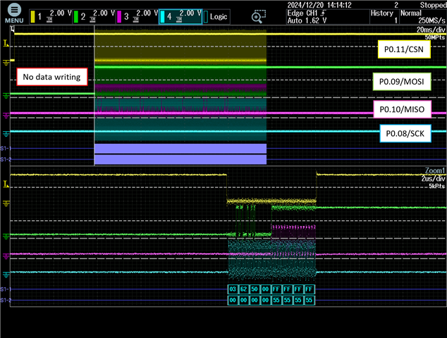
Also, even if you change the hardware to always have the PSRAM powered on (P0.11/CSN:Always High), the above procedure will not execute the first data write.

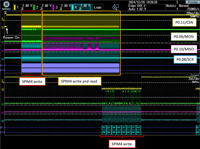
If you comment out "sense-edge-mask" in the Device Tree, the problem of this data not being written does not occur.
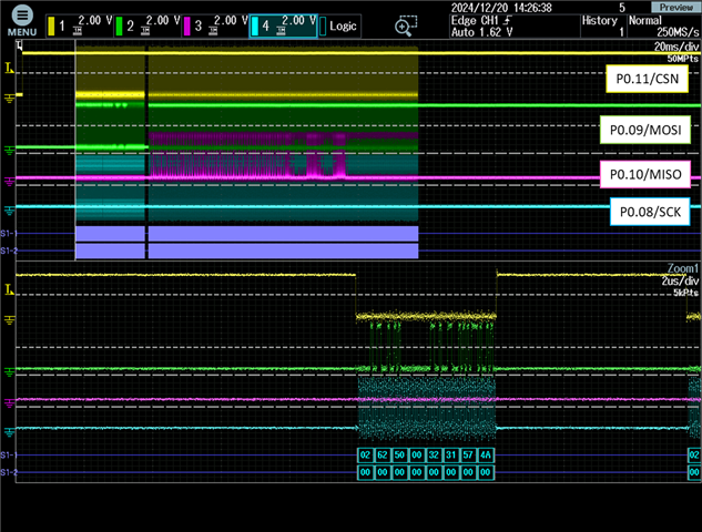
(It is possible that other pins are also behaving abnormally, but I have not been able to confirm this at present.)

Questions:

  1. If I mask the GPIOTE event in Devicetree as above, could it affect other peripherals such as SPIM?
  2. Is there another way to properly configure GPIOTE PORT events?

Best regard,

Parents Reply Children
  • Hello,

    The answers to the questions are as follows:

    1.How gpio_pin_configure() is called
    The configuration for the pins used for interrupts (P0.04, P0.28) is as follows:

    static struct gpio_callback ms_intrtc_cb_data;
    
    gpio_dev = device_get_binding(DT_LABEL(DT_NODELABEL(gpio0)));
    gpio_pin_configure(gpio_dev, 4, GPIO_INPUT | GPIO_PULL_UP | GPIO_ACTIVE_LOW);
    gpio_pin_interrupt_configure(gpio_dev, 4, GPIO_INT_EDGE_TO_ACTIVE);
    gpio_init_callback(&ms_intrtc_cb_data, RTC_interrupt, BIT(4));
    gpio_add_callback(gpio_dev, &ms_intrtc_cb_data);
    
    
    static struct gpio_callback intmems1_cb_data;
    
    gpio_dev_mems = device_get_binding(DT_LABEL(DT_NODELABEL(gpio0)));
    gpio_pin_configure(gpio_dev_mems, 28, GPIO_INPUT | GPIO_ACTIVE_LOW);
    gpio_pin_interrupt_configure(gpio_dev_mems, 28, GPIO_INT_EDGE_TO_INACTIVE);
    gpio_init_callback(&intmems1_cb_data, AccelMEMS_mems1_int, BIT(28));
    gpio_add_callback(gpio_dev_mems, &intmems1_cb_data);

    The configuration for the pins used with SPIM4 (P0.08/SCK, P0.09/MOSI, P0.10/MISO, P0.11/CSN) is as follows:

    static const nrfx_spim_t m_spim4 = NRFX_SPIM_INSTANCE(4);
    #define SPIM4_NODE  DT_NODELABEL(spi4)
    #define D_PSRAM_SEND_CLOCK  NRF_SPIM_FREQ_32M
    
    nrfx_spim_uninit(&m_spim4);
    nrfx_spim_config_t config = NRFX_SPIM_DEFAULT_CONFIG(
    	NRFX_SPIM_PIN_NOT_USED,
    	NRFX_SPIM_PIN_NOT_USED,
    	NRFX_SPIM_PIN_NOT_USED,
    	NRF_DT_GPIOS_TO_PSEL(SPIM4_NODE, cs_gpios)
    );
    config.mode = NRF_SPIM_MODE_0;
    config.skip_psel_cfg = true;
    config.use_hw_ss = true;
    config.frequency = D_PSRAM_SEND_CLOCK;
    
    nrfx_spim_init(&m_spim4, &config, NULL, NULL); 
    
    NRF_SPIM4->PSEL.CSN = 0x0000000B;

    2.Callback that triggers the SPIM transfer
    The data transfer using SPIM4 is triggered by the following callback:

    nrfx_spim_xfer_desc_t xfer_desc = NRFX_SPIM_XFER_TX(
        	access_write, 
    	D_APS6404L_COMMAND_OFFSET_DATA_BYTE0 + D_PSRAM_NRFX_LENGTH_MAX
    );
    
    nrfx_spim_xfer(&m_spim4, &xfer_desc, 0);

    If there's any other information you need, please let me know.

    Best regards,

Related