How to properly configure GPIOTE PORT events

Hello,

I am using the following device and development kit:

  • Device: NORA-B106-00B (nRF5340)
  • nRF Connect SDK: 2.0.2

Currently, I am trying to use GPIOTE PORT events to detect interrupts on pins P0.04 and P0.28.

The mask for pins that do not use GPIOTE is defined in the Devicetree as follows:

&gpio0 {
	status = "okay";
	sense-edge-mask = < 0x10000010 >; //Mask GPIOTE events other than P0.04 and P0.28
};

Also, among the pins that mask GPIOTE events are the following pins used as SPIM4.

  • P0.08/SCK
  • P0.09/MOSI
  • P0.10/MISO
  • P0.11/CSN

I have PSRAM connected to SPIM4, which is turned off when idle and turned on when in use.

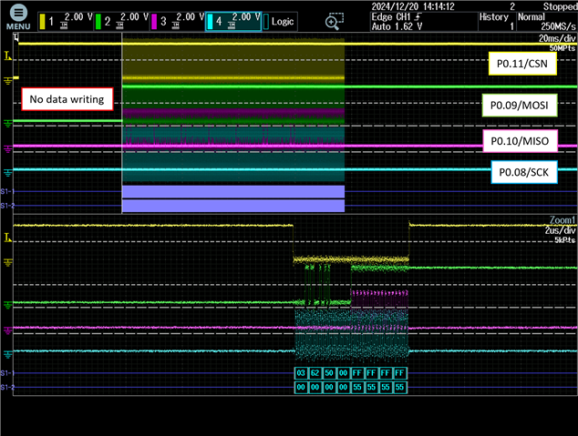
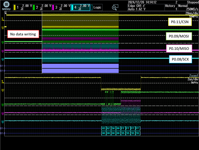
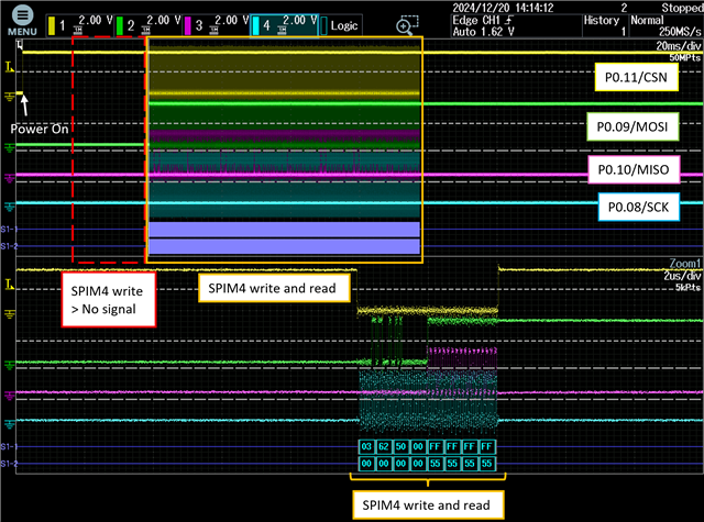
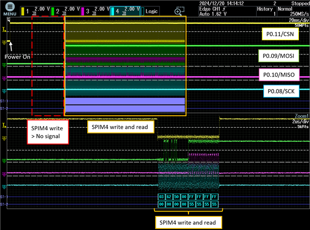
Here, if you try to write data using the nrfx spim driver after the power is turned on (P0.11/CSN:High), the write will not be executed as shown below, but if you read the data immediately after, the SPIM4 works and reads the data.

(Since no data has been written, the data read will be an undefined value.)
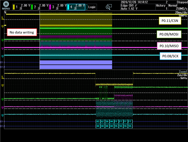
Also, even if you change the hardware to always have the PSRAM powered on (P0.11/CSN:Always High), the above procedure will not execute the first data write.

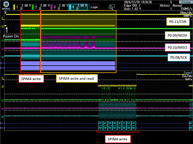
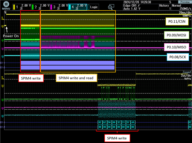
If you comment out "sense-edge-mask" in the Device Tree, the problem of this data not being written does not occur.
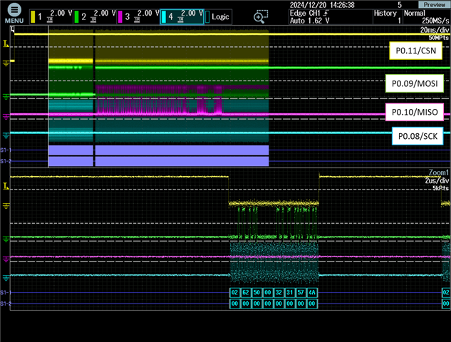
(It is possible that other pins are also behaving abnormally, but I have not been able to confirm this at present.)

Questions:

  1. If I mask the GPIOTE event in Devicetree as above, could it affect other peripherals such as SPIM?
  2. Is there another way to properly configure GPIOTE PORT events?

Best regard,

Parents
  • Hi

    Which pins are you trying to configure with sense-edge-mask?

    Is there another way to properly configure GPIOTE PORT events?

    You can always use nrfx directly, as seen in this sample.

  • Hello,

    Thank you for your reply.

    I am trying to configure edge detection for P0.04 and P0.28 with sense-edge-mask.

    I thought that I could mask the GPIOTE edge detection of other pins with the device tree settings above.

    The sample you introduced does not seem to use sense-edge-mask, but is it correct to understand that if you configure GPIOTE only for the pins used for interrupts, there is no need to mask other pins?

    Best regard,

  • Hello,

    The answers to the questions are as follows:

    1.How gpio_pin_configure() is called
    The configuration for the pins used for interrupts (P0.04, P0.28) is as follows:

    static struct gpio_callback ms_intrtc_cb_data;
    
    gpio_dev = device_get_binding(DT_LABEL(DT_NODELABEL(gpio0)));
    gpio_pin_configure(gpio_dev, 4, GPIO_INPUT | GPIO_PULL_UP | GPIO_ACTIVE_LOW);
    gpio_pin_interrupt_configure(gpio_dev, 4, GPIO_INT_EDGE_TO_ACTIVE);
    gpio_init_callback(&ms_intrtc_cb_data, RTC_interrupt, BIT(4));
    gpio_add_callback(gpio_dev, &ms_intrtc_cb_data);
    
    
    static struct gpio_callback intmems1_cb_data;
    
    gpio_dev_mems = device_get_binding(DT_LABEL(DT_NODELABEL(gpio0)));
    gpio_pin_configure(gpio_dev_mems, 28, GPIO_INPUT | GPIO_ACTIVE_LOW);
    gpio_pin_interrupt_configure(gpio_dev_mems, 28, GPIO_INT_EDGE_TO_INACTIVE);
    gpio_init_callback(&intmems1_cb_data, AccelMEMS_mems1_int, BIT(28));
    gpio_add_callback(gpio_dev_mems, &intmems1_cb_data);

    The configuration for the pins used with SPIM4 (P0.08/SCK, P0.09/MOSI, P0.10/MISO, P0.11/CSN) is as follows:

    static const nrfx_spim_t m_spim4 = NRFX_SPIM_INSTANCE(4);
    #define SPIM4_NODE  DT_NODELABEL(spi4)
    #define D_PSRAM_SEND_CLOCK  NRF_SPIM_FREQ_32M
    
    nrfx_spim_uninit(&m_spim4);
    nrfx_spim_config_t config = NRFX_SPIM_DEFAULT_CONFIG(
    	NRFX_SPIM_PIN_NOT_USED,
    	NRFX_SPIM_PIN_NOT_USED,
    	NRFX_SPIM_PIN_NOT_USED,
    	NRF_DT_GPIOS_TO_PSEL(SPIM4_NODE, cs_gpios)
    );
    config.mode = NRF_SPIM_MODE_0;
    config.skip_psel_cfg = true;
    config.use_hw_ss = true;
    config.frequency = D_PSRAM_SEND_CLOCK;
    
    nrfx_spim_init(&m_spim4, &config, NULL, NULL); 
    
    NRF_SPIM4->PSEL.CSN = 0x0000000B;

    2.Callback that triggers the SPIM transfer
    The data transfer using SPIM4 is triggered by the following callback:

    nrfx_spim_xfer_desc_t xfer_desc = NRFX_SPIM_XFER_TX(
        	access_write, 
    	D_APS6404L_COMMAND_OFFSET_DATA_BYTE0 + D_PSRAM_NRFX_LENGTH_MAX
    );
    
    nrfx_spim_xfer(&m_spim4, &xfer_desc, 0);

    If there's any other information you need, please let me know.

    Best regards,

  • Hi there,

    I'll be taking over this case from Sigurd. 

    I've read the post and the comments, and here some comments and questions I have:

    My understanding is that you are trying to write to some external memory using SPIM peripheral, while at the same time enabling the PORT event for two other GPIOs.

    It's not entirely clear for me what the issue is, but it seems like using the sense-edge-mask is effecting the SPIM transfer somehow, is this correct?

    Here, if you try to write data using the nrfx spim driver after the power is turned on (P0.11/CSN:High), the write will not be executed as shown below, but if you read the data immediately after, the SPIM4 works and reads the data.

    (Since no data has been written, the data read will be an undefined value.)

    Here I can see data is being written on MISO and data being returned on MOSI. So this is a successful write and read? Is this with sense-edge-mask disabled?

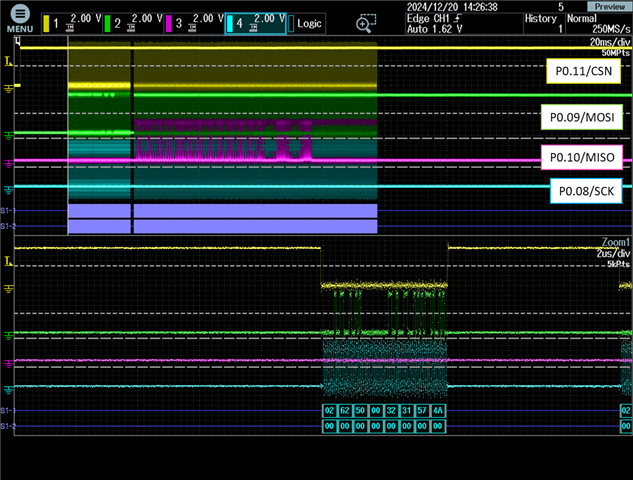
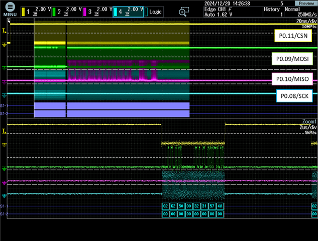
    If you comment out "sense-edge-mask" in the Device Tree, the problem of this data not being written does not occur.

    (It is possible that other pins are also behaving abnormally, but I have not been able to confirm this at present.)

    Here I see that data is being written on MOSI but no data is being returned on MISO. Is this with sense-edge-mask enabled?

    The relation between the SPIM transfer and the PORT events interrupts is not clear, can you explain it?

    Are you triggering the SPIM transfer from one of the interrupts on either P0.04 and P0.28?

    Looking at your code it looks somewhat ok, but I would prefer if you checked the return value from the gpio functions and confirm that none of them returns an error. Can you do that?

    sst_S.Sakamoto said:
    sense-edge-mask enabled disabled GPIOTE CONFIG[7] 0x00000000 0x00011C00 GPIOTE CONFIG[6] 0x00000000 0x00020401

    The value for GPIOTE CONFIG[7] is correct in that it disables the IN event and sets up PORT event for P0.28 for Lo-to-High as you do in your code.

    However for GPIOTE CONFIG [6] it's not correct for some reason. For some reason MODE field is set to EVENT for P0.04 but it should be disabled.

    Can you try to comment out the last part for P0.28 and then read out the CONFIG registers and se if they have changed?

    static struct gpio_callback ms_intrtc_cb_data;
    
    gpio_dev = device_get_binding(DT_LABEL(DT_NODELABEL(gpio0)));
    gpio_pin_configure(gpio_dev, 4, GPIO_INPUT | GPIO_PULL_UP | GPIO_ACTIVE_LOW);
    gpio_pin_interrupt_configure(gpio_dev, 4, GPIO_INT_EDGE_TO_ACTIVE);
    gpio_init_callback(&ms_intrtc_cb_data, RTC_interrupt, BIT(4));
    gpio_add_callback(gpio_dev, &ms_intrtc_cb_data);
    
    
    /*static struct gpio_callback intmems1_cb_data;
    
    gpio_dev_mems = device_get_binding(DT_LABEL(DT_NODELABEL(gpio0)));
    gpio_pin_configure(gpio_dev_mems, 28, GPIO_INPUT | GPIO_ACTIVE_LOW);
    gpio_pin_interrupt_configure(gpio_dev_mems, 28, GPIO_INT_EDGE_TO_INACTIVE);
    gpio_init_callback(&intmems1_cb_data, AccelMEMS_mems1_int, BIT(28));
    gpio_add_callback(gpio_dev_mems, &intmems1_cb_data);*/

    best regards
    Jared

  • Hello Jared,

    Thank you for your reply.

    I will answer the questions you have asked.

    It's not entirely clear for me what the issue is, but it seems like using the sense-edge-mask is effecting the SPIM transfer somehow, is this correct?

    Yes, that understanding is correct.

    Here I can see data is being written on MISO and data being returned on MOSI. So this is a successful write and read? Is this with sense-edge-mask disabled?

    No, data is not being written here, only the subsequent write and read operations are successful.

    Additionally, the sense-edge-mask is enabled at this time.

    Here I see that data is being written on MOSI but no data is being returned on MISO. Is this with sense-edge-mask enabled?

    No, data is being successfully written here, and the subsequent write and read operations are also successful.

    Additionally, the sense-edge-mask is disabled at this time.

    The relation between the SPIM transfer and the PORT events interrupts is not clear, can you explain it?

    Are you triggering the SPIM transfer from one of the interrupts on either P0.04 and P0.28?

    This SPIM transfer is not triggered by PORT event interrupts.

    It is processed in response to commands from the BLE.

    Looking at your code it looks somewhat ok, but I would prefer if you checked the return value from the gpio functions and confirm that none of them returns an error. Can you do that?

    I think that’s possible.

    The value for GPIOTE CONFIG[7] is correct in that it disables the IN event and sets up PORT event for P0.28 for Lo-to-High as you do in your code.

    However for GPIOTE CONFIG [6] it's not correct for some reason. For some reason MODE field is set to EVENT for P0.04 but it should be disabled.

    Can you try to comment out the last part for P0.28 and then read out the CONFIG registers and se if they have changed?

    P0.04 is configured to be used as a PORT event for interrupt handling.
    I think it’s possible to comment out the part you mentioned and check the CONFIG registers, but I am puzzled by the fact that when the sense-edge-mask is enabled, the GPIOTE CONFIG register is unset during idle, whereas when the sense-edge-mask is disabled, the GPIOTE CONFIG register is set during idle.


    In the original source code, SPIM is initialized immediately after startup and enters idle state, then wakes up in response to a command from BLE and performs a SPIM transfer.

    Here, I confirmed that if we change the code to re-initialize SPIM just before a SPIM transfer, SPIM transfer will be performed normally even when sense-edge-mask is enabled.

    In addition, I measured the CPU (nRF5340) current consumption in idle mode with sense-edge-mask enabled and disabled, and the results are shown below.

    sense-edge-mask Current Consumption (μA)
    Enabled 1.2
    Disabled 31.9

    When the sense-edge-mask is enabled, the CPU current consumption during idle is significantly lower (1.2 μA) compared to when it is disabled (31.9 μA).

    Questions:

    1. Are the registers retained when the current consumption during idle is low (sense-edge-mask enabled)?
    2. Do I need to reconfigure registers such as GPIO when I wake up from idle?

    Best regards,

  • Hi,

    First some answers to your questions:

    sst_S.Sakamoto said:

    In the original source code, SPIM is initialized immediately after startup and enters idle state, then wakes up in response to a command from BLE and performs a SPIM transfer.

    Here, I confirmed that if we change the code to re-initialize SPIM just before a SPIM transfer, SPIM transfer will be performed normally even when sense-edge-mask is enabled.

    In addition, I measured the CPU (nRF5340) current consumption in idle mode with sense-edge-mask enabled and disabled, and the results are shown below.

    Ok, that is a good observation and maybe a temporal fix until we find the root cause. Somehow using sense-edge-mask seems to be affecting the SPIM configuration. 

    Is there any difference if you change P0.04 to some other GPIO?

    Less current consumption for sense-edge-mask enabled makes sense since it will not use the IN event to detect the interrupt but rather a PORT event which use less power.

    sst_S.Sakamoto said:

    Questions:

    1. Are the registers retained when the current consumption during idle is low (sense-edge-mask enabled)?
    2. Do I need to reconfigure registers such as GPIO when I wake up from idle?
    1. Registers are retained when going to SYSTEM ON (IDLE SLEEP) mode.
    2. No only when you go to system off will it be reset.
    sst_S.Sakamoto said:
    but I am puzzled by the fact that when the sense-edge-mask is enabled, the GPIOTE CONFIG register is unset during idle, whereas when the sense-edge-mask is disabled, the GPIOTE CONFIG register is set during idle.

    My observation was that the GPIOTE CONFIG register is not set correctly for P0.04. I'm not sure why. Can you try my suggestion in my previous reply to remove the P0.28 part and see if it has any effect on if P0.04 GPIOTE CONFIG is set correctly. Can you also try to change from P0.04 to another GPIO for example P0.06 and see if it behaves the same. 

    sst_S.Sakamoto said:

    Here I can see data is being written on MISO and data being returned on MOSI. So this is a successful write and read? Is this with sense-edge-mask disabled?

    No, data is not being written here, only the subsequent write and read operations are successful.

    Additionally, the sense-edge-mask is enabled at this time.

     I see CS (Yellow) goes down, data is being sent on MOSI(Light Green) and data is being received on MISO(Pink).

    sst_S.Sakamoto said:

    Here I see that data is being written on MOSI but no data is being returned on MISO. Is this with sense-edge-mask enabled?

    No, data is being successfully written here, and the subsequent write and read operations are also successful.

    Additionally, the sense-edge-mask is disabled at this time.

    Here I see CS(Yellow) goes down, data is being sent on MOSI (Light Green) twice but no data received on MISO (Pink). I assume the bottom Blue line is SCLK. 

    Is this correct? 

  • Hello Jared,

    Thank you for answering my question.

    Questions:

    1. Are the registers retained when the current consumption during idle is low (sense-edge-mask enabled)?
    2. Do I need to reconfigure registers such as GPIO when I wake up from idle?
    1. Registers are retained when going to SYSTEM ON (IDLE SLEEP) mode.
    2. No only when you go to system off will it be reset.

    I understood that the registers will retain their settings as long as the system does not go to off.


    Is there any difference if you change P0.04 to some other GPIO?

    Less current consumption for sense-edge-mask enabled makes sense since it will not use the IN event to detect the interrupt but rather a PORT event which use less power.

    My observation was that the GPIOTE CONFIG register is not set correctly for P0.04. I'm not sure why. Can you try my suggestion in my previous reply to remove the P0.28 part and see if it has any effect on if P0.04 GPIOTE CONFIG is set correctly. Can you also try to change from P0.04 to another GPIO for example P0.06 and see if it behaves the same. 

    I will check these, so please wait.


    sst_S.Sakamoto said:

    Here I can see data is being written on MISO and data being returned on MOSI. So this is a successful write and read? Is this with sense-edge-mask disabled?

    No, data is not being written here, only the subsequent write and read operations are successful.

    Additionally, the sense-edge-mask is enabled at this time.

     I see CS (Yellow) goes down, data is being sent on MOSI(Light Green) and data is being received on MISO(Pink).

    sst_S.Sakamoto said:

    Here I see that data is being written on MOSI but no data is being returned on MISO. Is this with sense-edge-mask enabled?

    No, data is being successfully written here, and the subsequent write and read operations are also successful.

    Additionally, the sense-edge-mask is disabled at this time.

    Here I see CS(Yellow) goes down, data is being sent on MOSI (Light Green) twice but no data received on MISO (Pink). I assume the bottom Blue line is SCLK. 

    Is this correct? 

    Sorry, my explanation was insufficient.

    Details of the SPIM signal line capture are shown below.

    • sense-edge-mask enabled

    • sense-edge-mask disabled

    The SPIM communication processing operation is as follows:

    Power on > SPIM write (SCK frequency:32MHz) > SPIM write and read (SCK frequency:16MHz)

    From the above, we can see that when sense-edge-mask is enabled, the SPIM signal line is not output in the place where SPIM write should operate.

    The colors of each line are correct as you said.


    Please let me know if there is anything else to check.

    I will continue to add information here if there is any progress.

    Best regards,

Reply
  • Hello Jared,

    Thank you for answering my question.

    Questions:

    1. Are the registers retained when the current consumption during idle is low (sense-edge-mask enabled)?
    2. Do I need to reconfigure registers such as GPIO when I wake up from idle?
    1. Registers are retained when going to SYSTEM ON (IDLE SLEEP) mode.
    2. No only when you go to system off will it be reset.

    I understood that the registers will retain their settings as long as the system does not go to off.


    Is there any difference if you change P0.04 to some other GPIO?

    Less current consumption for sense-edge-mask enabled makes sense since it will not use the IN event to detect the interrupt but rather a PORT event which use less power.

    My observation was that the GPIOTE CONFIG register is not set correctly for P0.04. I'm not sure why. Can you try my suggestion in my previous reply to remove the P0.28 part and see if it has any effect on if P0.04 GPIOTE CONFIG is set correctly. Can you also try to change from P0.04 to another GPIO for example P0.06 and see if it behaves the same. 

    I will check these, so please wait.


    sst_S.Sakamoto said:

    Here I can see data is being written on MISO and data being returned on MOSI. So this is a successful write and read? Is this with sense-edge-mask disabled?

    No, data is not being written here, only the subsequent write and read operations are successful.

    Additionally, the sense-edge-mask is enabled at this time.

     I see CS (Yellow) goes down, data is being sent on MOSI(Light Green) and data is being received on MISO(Pink).

    sst_S.Sakamoto said:

    Here I see that data is being written on MOSI but no data is being returned on MISO. Is this with sense-edge-mask enabled?

    No, data is being successfully written here, and the subsequent write and read operations are also successful.

    Additionally, the sense-edge-mask is disabled at this time.

    Here I see CS(Yellow) goes down, data is being sent on MOSI (Light Green) twice but no data received on MISO (Pink). I assume the bottom Blue line is SCLK. 

    Is this correct? 

    Sorry, my explanation was insufficient.

    Details of the SPIM signal line capture are shown below.

    • sense-edge-mask enabled

    • sense-edge-mask disabled

    The SPIM communication processing operation is as follows:

    Power on > SPIM write (SCK frequency:32MHz) > SPIM write and read (SCK frequency:16MHz)

    From the above, we can see that when sense-edge-mask is enabled, the SPIM signal line is not output in the place where SPIM write should operate.

    The colors of each line are correct as you said.


    Please let me know if there is anything else to check.

    I will continue to add information here if there is any progress.

    Best regards,

Children
  • Hi,

    sst_S.Sakamoto said:

    I understood that the registers will retain their settings as long as the system does not go to off.

    Yes that is correct.

    sst_S.Sakamoto said:
    I will check these, so please wait.

    ok!

    sst_S.Sakamoto said:

    Sorry, my explanation was insufficient.

    Details of the SPIM signal line capture are shown below.

    • sense-edge-mask enabled

    • sense-edge-mask disabled

    The SPIM communication processing operation is as follows:

    Power on > SPIM write (SCK frequency:32MHz) > SPIM write and read (SCK frequency:16MHz)

    From the above, we can see that when sense-edge-mask is enabled, the SPIM signal line is not output in the place where SPIM write should operate.

    The colors of each line are correct as you said.

    ah now I understand, thank you fort the clarification!

    sst_S.Sakamoto said:

    Please let me know if there is anything else to check.

    I will continue to add information here if there is any progress.

    If possible maybe you could provide a very simple example that reproduce the issue? Maybe something I can test on my development kit?

    regards

    Jared 

  • Hello Jared,

    Sorry for the late reply.

    I tried the method introduced in [135] SPIM: No output from SPIM4 at the link below:

    [135] SPIM: No output from SPIM4

    By implementing this procedure, I confirmed that the first SPIM4 write operation now works correctly even when sense-edge-mask is enabled.

    If there is any official documentation or known errata about using this register in low-power scenarios, I would greatly appreciate any information you can provide.

    Thank you very much for your help.

    Best regards,

  • Hi,

    We don't have any more information publicly available than what is already stated in errata. 

    Great that it now works, maybe you can show me how you have implemented this errata and I can see if it's ok?

    regards

    Jared 

  • Hello Jared,

    Thank you for your response. I’ve implemented the workaround based on the information provided in [135] (“SPIM: No output from SPIM4”). Below is an overview of how I applied the errata workaround in my code:

    // Enable SPIM for PSRAM
    *(volatile uint32_t *)0x5000ac04 = 1;
    nrf_spim_enable(D_PSRAM_SPIM_PERIPHERAL);
    
    // Disable SPIM for PSRAM
    nrf_spim_disable(D_PSRAM_SPIM_PERIPHERAL);
    *(volatile uint32_t *)0x5000ac04 = 0;

    With these changes, the first write operation to external memory via SPIM4 now works consistently when the sense-edge-mask is enabled.

    Could you please review this implementation and let me know if there’s any recommended improvement or best practice I might be missing?

    Best regards,

Related