I have an Adafruit Feather nRF52840 which I'm trying to use to transmit data over a UART serial connection to a Raspberry Pi. The Raspberry Pi is running a Python test script (details below) which configures its serial port per the MIDI specification which says:
"The hardware MIDI interface operates at 31.25 (+/- 1%) Kbaud, asynchronous, with a start bit, 8 data bits (D0 to D7), and a stop bit. This makes a total of 10 bits for a period of 320 microseconds per serial byte. The start bit is a logical 0 (current on) and the stop bit is a logical 1 (current off)".
My Zephyr code configures the nRF52840 in the same way. I then send 8 bytes with known values. The Raspberry Pi script prints what it receives to the console.
The Pi is printing 5 times more bytes than are being transmitted and the byte values bear no resemblance to those that were transmitted. I believe this is indicative of a mismatch between the UART configs on the transmitting nRF52840 and the Pi.
Here's the Raspberry Pi receiver script:
import serial

ser = serial.Serial('/dev/ttyAMA0', baudrate=31250)

while True:

  data = ord(ser.read(1))
  print("Decimal: "+str(data)+"\t\tBinary: "+format(data,'008b')+"\t\tHex: 0x"+format(data,'02x'))
Note that I validated the Python script by connecting a commercial MIDI keyboard directly to the Pi and pressing a key (note=F3). The results were as expected and are presented here:
MIDI Keyboard sending NOTE ON then NOTE OFF to the Receiver (key played, F3)
Decimal: 144            Binary: 10010000                Hex: 0x90
Decimal: 65             Binary: 01000001                Hex: 0x41
Decimal: 52             Binary: 00110100                Hex: 0x34
Decimal: 128            Binary: 10000000                Hex: 0x80
Decimal: 65             Binary: 01000001                Hex: 0x41
Decimal: 59             Binary: 00111011                Hex: 0x3b

NOTE ON  is 1001nnnn 0kkkkkkk 0vvvvvvv where n is the channel, k is the note number and v is the velocity value.
NOTE OFF is 1000nnnn 0kkkkkkk 0vvvvvvv where n is the channel, k is the note number and v is the velocity value.

So the data received:
10010000    01000001    00110100 - NOTE ON  (channel 1), note=F3, velocity=52
10000000    01000001    00111011 - NOTE OFF (channel 1), note=F3, velocity=59

Results are as expected. Python script validated.
Here's my Zephyr code:
// C code
#include <zephyr/kernel.h>
#include <zephyr/drivers/uart.h>
#include <math.h>
/* Get UART1 device */
static const struct device *uart = DEVICE_DT_GET(DT_NODELABEL(uart1));
// 1200, 2400, 4800, 9600, 19200, 31250, 57600, 115200
#define BAUDRATE 31250
int main(void)
{
printk("uart_tx_text V1.3 - baudrate=%d\n",BAUDRATE);
if (!device_is_ready(uart)) {
printk("ERROR: uart1 is not ready\n");
return -1;
}
printk("UART1 is ready\n");
/* UART configuration */
const struct uart_config uart_cfg = {
.baudrate = BAUDRATE,
.parity = UART_CFG_PARITY_NONE,
.stop_bits = UART_CFG_STOP_BITS_1,
.data_bits = UART_CFG_DATA_BITS_8,
.flow_ctrl = UART_CFG_FLOW_CTRL_NONE
};
int ret = uart_configure(uart, &uart_cfg);
if (ret < 0) {
printk("ERROR configuring UART: %d",ret);
return ret;
}
printk("UART1 has been configured - start receiver now\n");
k_msleep(10000);
int p=0;
for (p=1; p<9;p++) {
uint8_t val=(pow(2,p)-1);
uart_poll_out(uart, val);
printk("TX Decimal: %d Hex: %02x\n",val, val);
}
return 0;
}
// DTS overlay
/*
* Copyright (c) 2025
* SPDX-License-Identifier: Apache-2.0
*/
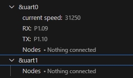
&uart1 {
compatible = "nordic,nrf-uarte";
status = "okay";
current-speed = <31250>;
pinctrl-0 = <&uart1_default>;
pinctrl-1 = <&uart1_sleep>;
pinctrl-names = "default", "sleep";
};
&pinctrl {
uart1_default: uart1_default {
group1 {
psels = <NRF_PSEL(UART_TX, 1, 10)>;
};
group2 {
psels = <NRF_PSEL(UART_RX, 1, 9)>;
bias-pull-up;
};
};
uart1_sleep: uart1_sleep {
group1 {
psels = <NRF_PSEL(UART_TX, 1, 10)>,
<NRF_PSEL(UART_RX, 1, 9)>;
low-power-enable;
};
};
};
// prj.conf
CONFIG_GPIO=y
CONFIG_SERIAL=y
CONFIG_UART_USE_RUNTIME_CONFIGURE=y
CONFIG_LOG=y
CONFIG_USE_SEGGER_RTT=y
CONFIG_SEGGER_RTT_PRINTF_BUFFER_SIZE=512
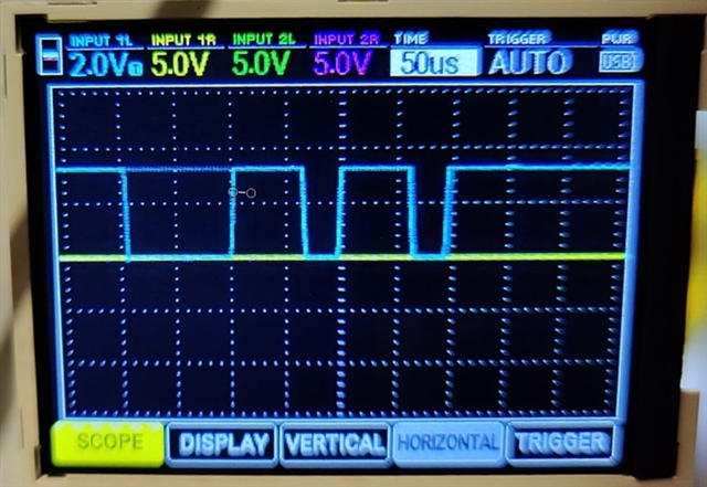
And here are my test results:
// output from the Adafruit Feather nRF52840
00> *** Booting nRF Connect SDK v3.1.1-e2a97fe2578a ***
00> *** Using Zephyr OS v4.1.99-ff8f0c579eeb ***
00> uart_tx_text V1.3 - baudrate=31250
00> UART1 is ready
00> UART1 has been configured - start receiver now
00> TX Decimal: 1 Hex: 01
00> TX Decimal: 3 Hex: 03
00> TX Decimal: 7 Hex: 07
00> TX Decimal: 15 Hex: 0f
00> TX Decimal: 31 Hex: 1f
00> TX Decimal: 63 Hex: 3f
00> TX Decimal: 127 Hex: 7f
00> TX Decimal: 255 Hex: ff

// Output from the Raspberry Pi receiver script
Receiver:
Decimal: 129            Binary: 10000001                Hex: 0x81
Decimal: 78             Binary: 01001110                Hex: 0x4e
Decimal: 198            Binary: 11000110                Hex: 0xc6
Decimal: 39             Binary: 00100111                Hex: 0x27
Decimal: 237            Binary: 11101101                Hex: 0xed
Decimal: 136            Binary: 10001000                Hex: 0x88
Decimal: 139            Binary: 10001011                Hex: 0x8b
Decimal: 200            Binary: 11001000                Hex: 0xc8
Decimal: 220            Binary: 11011100                Hex: 0xdc
Decimal: 107            Binary: 01101011                Hex: 0x6b
Decimal: 239            Binary: 11101111                Hex: 0xef
Decimal: 11             Binary: 00001011                Hex: 0x0b
Decimal: 224            Binary: 11100000                Hex: 0xe0
Decimal: 196            Binary: 11000100                Hex: 0xc4
Decimal: 107            Binary: 01101011                Hex: 0x6b
Decimal: 207            Binary: 11001111                Hex: 0xcf
Decimal: 11             Binary: 00001011                Hex: 0x0b
Decimal: 113            Binary: 01110001                Hex: 0x71
Decimal: 198            Binary: 11000110                Hex: 0xc6
Decimal: 107            Binary: 01101011                Hex: 0x6b
Decimal: 207            Binary: 11001111                Hex: 0xcf
Decimal: 11             Binary: 00001011                Hex: 0x0b
Decimal: 224            Binary: 11100000                Hex: 0xe0
Decimal: 198            Binary: 11000110                Hex: 0xc6
Decimal: 59             Binary: 00111011                Hex: 0x3b
Decimal: 207            Binary: 11001111                Hex: 0xcf
Decimal: 3              Binary: 00000011                Hex: 0x03
Decimal: 232            Binary: 11101000                Hex: 0xe8
Decimal: 198            Binary: 11000110                Hex: 0xc6
Decimal: 59             Binary: 00111011                Hex: 0x3b
Decimal: 207            Binary: 11001111                Hex: 0xcf
Decimal: 139            Binary: 10001011                Hex: 0x8b
Decimal: 232            Binary: 11101000                Hex: 0xe8
Decimal: 228            Binary: 11100100                Hex: 0xe4
Decimal: 255            Binary: 11111111                Hex: 0xff
My UART config params look correct in my Zephyr C code and I am not getting an error when I call uart_configure. And yet the evidence would suggest that the configuration is not being set as requested. The transmitting nRF52840 and receiving Pi are presumably not using the same parameters which is why the Pi reports nonsense results.
Note that this Pi has been used for MIDI applications many times before and is therefore a reliable, known quantity. My validation test also verifies that the problem is not at the receiver end of the communication.
Could someone please help with this? Is this a Zephyr bug? Or is it my code?
Thanks in anticipation