nRF54LM20B UART Communication

Hi Team,

Currently I am working with nRF54LM20 DK. And tried to import and use echo bot example from SDK. 
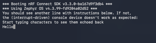
And modified the overlay file as per the UART pin changes required for my application. But I am not able to see any UART prints on console.
Adding overlay file contents here

&pinctrl {

    uart21_default: uart21_default {
        group1 {
            psels = <
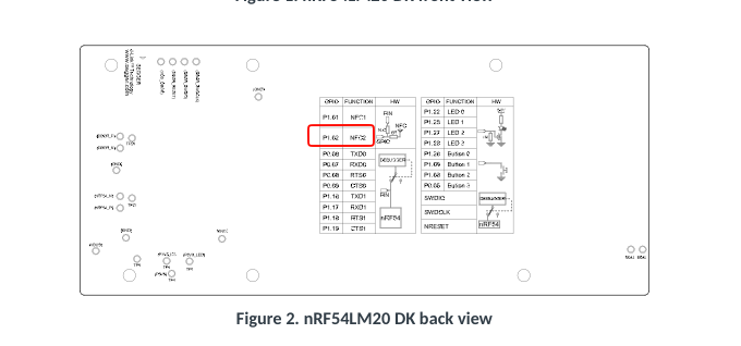
                NRF_PSEL(UART_TX, 1, 2)   /* TX → P1.02 */
                NRF_PSEL(UART_RX, 1, 3)   /* RX → P1.03 */
            >;
        };
    };

    uart21_sleep: uart21_sleep {
        group1 {
            psels = <
                NRF_PSEL(UART_TX, 1, 2)
                NRF_PSEL(UART_RX, 1, 3)
            >;
            low-power-enable;
        };
    };
};

&uart21 {
    status = "okay";
    current-speed = <115200>;

    pinctrl-0 = <&uart21_default>;
    pinctrl-1 = <&uart21_sleep>;
    pinctrl-names = "default", "sleep";
};


/ {
    chosen {
        zephyr,console = &uart21;
    };
};

Please let me know the issue I am facing to use this bus.

Thanks and regards,

Vinay

Parents
  • Hi,

    Do you have an external UART-USB bridge connected to these pins to bridge the serial communication to your PC? If not, you need to use the default pin assignments to use the on-board J-Link as your serial bridge, see https://docs.nordicsemi.com/bundle/ug_nrf54lm20_dk/page/UG/nRF54LM20_DK/program_debug/virtual_serial_ports.html

    Best regards,

    Vidar

  • Hi Vidar, 

    Yes we have external UART-USB Bridge which we have connected to PC and checking the output. But we are not able to see any logs printed on the console.

    Please need your guidance on this.

    Thanks and regards,

    Vinay

  • Hi Vinay,

    I see you are still using P1.02 for UART_TX, which as I mentioned in my previous reply, isn't connected to the pin header by default:

    Is there a reason for why you cannot use the default pin assigments with the on-board Jlink serial bridge?

    Regards,

    Vidar

  • Hi Vidar,

    Thank you for your reply.

    Yes because we are using nRF54LM20 DK because we are going to build a custom board using nRF54LM20B. So we have used other pins for different usage. Ok I have tried this and still no output.

    &pinctrl {
        uart20_default: uart20_default {
            group1 {
                psels = <
                    NRF_PSEL(UART_TX, 1, 5)
                    NRF_PSEL(UART_RX, 1, 6)
                >;
            };
        };
    
        uart20_sleep: uart20_sleep {
            group1 {
                psels = <
                    NRF_PSEL(UART_TX, 1, 5)
                    NRF_PSEL(UART_RX, 1, 6)
                >;
                low-power-enable;
            };
        };
    };
    
    &uart20 {
        compatible = "nordic,nrf-uarte";
        status = "okay";
        current-speed = <115200>;
    
        pinctrl-0 = <&uart20_default>;
        pinctrl-1 = <&uart20_sleep>;
        pinctrl-names = "default", "sleep";
    };

    Please let me know why I am facing this issue.

    Thanks and regards,

    Vinay

  • Hi Vinay,

    P1.5 and P1.6 are not assigned to any specific functionality on the DK, so you can use them freely. As for why it is not working, it is difficult to say without more debugging information. Have you verified that your serial bridge is working and that the connections are correct (for example, could TX and RX be swapped)?

    I quickly tested the echo_bot sample with the following DT overlay: 

    &pinctrl {
        uart20_default: uart20_default {
            group1 {
                psels =
                    <NRF_PSEL(UART_TX, 1, 5)>,
                    <NRF_PSEL(UART_RX, 1, 6)>;
            };
            /delete-node/ group2;
        };
    
        uart20_sleep: uart20_sleep {
            group1 {
                psels = <NRF_PSEL(UART_RX, 1, 6)>;
                low-power-enable;
            };
            group2 {
                psels = <NRF_PSEL(UART_TX, 1, 5)>;
                low-power-enable;
                bias-pull-up;
            };
        };
    };

    I used jumper wires to connect P1.16 to P1.5 and P1.17 to P1.6 in order to use the on-board serial bridge.

    Console output:

    Hex file from my build:

    echo_bot.hex

    Best regards,

    Vidar

  • Hi Vidar,

    I have used hex file shared by you and flashed it to nRF54LM20 DK using Programmer. And connected a logic analyzer to RX,TX and Grnd and tried to see the changes in RX, TX lines. 
    But could not able to detect any changes in line. Its only high flat line.

    Please let me know Console output you have shown is from COM ports detected when you connect USB. Or external UART-USB Converter.

    Thanks and regards,

    Vinay

  • Hi Vinay,

    a logic analyzer to RX,TX and Grnd and tried to see the changes in RX, TX lines. 

    So the logic trace isn't showing anything when the external serial bridge is sending data either? Keep in mind that this sample only prints the boot banner and the info messages once at startup. After that, it will only echo any received data.

    Please let me know Console output you have shown is from COM ports detected when you connect USB. Or external UART-USB Converter.

    I am using the on-board bridge as said in my previous response. See board picture for the connections I made. 

Reply
  • Hi Vinay,

    a logic analyzer to RX,TX and Grnd and tried to see the changes in RX, TX lines. 

    So the logic trace isn't showing anything when the external serial bridge is sending data either? Keep in mind that this sample only prints the boot banner and the info messages once at startup. After that, it will only echo any received data.

    Please let me know Console output you have shown is from COM ports detected when you connect USB. Or external UART-USB Converter.

    I am using the on-board bridge as said in my previous response. See board picture for the connections I made. 

Children
Related