This post is older than 2 years and might not be relevant anymore
More Info: Consider searching for newer posts

nRF52832 Custom Board Development Issues

Hi All!

I have been working on bringing-up a custom manufactured nRF52832 board. I have with me 6 boards, the first 3 are working fine, the other 3 are not. In both cases, the components and the procedure used is the same. I've first worked with the nRF52 Development Kit and it worked fine. The boards are designed according to the reference schematics provided by Nordic. Please find attached the schematic of my design for the board.

Node-nRF52832.pdf

Some more info on what I'm using to flash the code:

Platform -> Linux, Compiler -> armgcc, soft-device -> s132

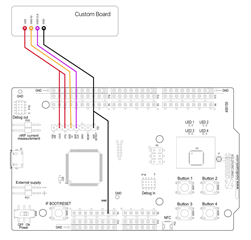
I'm able to flash the "blinky" example code in my custom boards successfully. The path is "nRF5_SDK_15.0.0_a53641a/examples/peripheral/blinky" by connecting its SWD pins to the nRF52 Development Kit's SWD pins as seen in the picture below. The outputs were observed on 3 of the 6 boards while the other 3 failed to respond. ( Please note that all 6 boards flashed successfully)

My questions are:

1. Why 3 of the 6 boards would work, and the other 3 would not?

2. To troubleshoot this, I started desoldering the crystals, first the 32.768 kHz and then the 32 MHz. And still flash happened successfully when no external crystals were connected. Is this behavior normal?

3. Can you suggest particular areas to concentrate on, so I can troubleshoot in an easier way and in lesser time?

Thanks in advance.

Best Regards,

Karan

Parents Reply Children
  • I've taken a second look, and except for the before mentioned R14 and R15, it looks correct.

  • Hi Ketiljo,

    Sorry about the delay. I've been having some difficulties with logging in on the devzone.

    So the nRF52832 chip is now responding after we changed the crystal to the Murata XRCGB32M000F2P10R0 (Nordic confirmed) 32MHz crystal. However, this does not clear my doubt of what exactly was causing the issue. And since we will be going into mass production soon after the development is finished, we need to make sure we leave no loose ends which might backfire later. I hope you understand.

    Some points I'm unable to understand:

    1. I had replaced the crystal with another part before(different part number) and the nRF52 still didnt respond. Why would it respond to only this particular Murata crystal?

    2. When I replaced the crystal in the working board with the crystal from the non-working board, the board still responded. If the crystal was defected, the working board would stop responding right?

    3. Why 3 of my custom boards would respond, whereas the other 3 would not?

    4. The 3 working boards were responding with the "blinky" code even without any crystals connected to the nRF52832. I understand this must be because of the internal crystals but if it is the case, shouldnt it also work when the crystal was defected?

    Best,

    Karan

  • Remember that the value of the load capacitors must match the crystal. The Murata XRCGB32M000F2P10R0 is a 6 pF crystal, so the load caps must be 8.2 pF each. Using this part number isn't necessary for correct operation, but using a crystal within the spec and with the correct load caps is needed. 

    No idea why it doesn't always work. Check the soldering.

    The blinky example doesn't use the external crystal, only the internal RC oscillator. The radio will _always_ request the crystal oscillator to be started.

Related