
Hello,
I am trying to code nRF52840- DK with MAX30003 ECG Board Using SPI. I have referred Arduino Uno Code for MAX30003 ECG.
I need some help for Driver Development if anybody worked on this please share any info.
Thanks and Regards,
Rohit
Hello,
I am trying to code nRF52840- DK with MAX30003 ECG Board Using SPI. I have referred Arduino Uno Code for MAX30003 ECG.
I need some help for Driver Development if anybody worked on this please share any info.
Thanks and Regards,
Rohit


Hey Rohit,
Either you answer the questions asked by Nordic staff or community members or you wont get any help from us. We can only help you help yourself. If you do not want our help please refrain from using our forum. It will not help you to keep posting the same question in new threads without engaging in any conversation in your ongoing thread:
See the public duplicates:
https://devzone.nordicsemi.com/f/nordic-q-a/39021/max30003-ecg-with-nrf52840
https://devzone.nordicsemi.com/f/nordic-q-a/39063/spi-communication-with-max30003-ecg-reg_read_write
I have got a few tips for your current project:
Here's an abstract architecture of your FW with regards to the MAX30003:
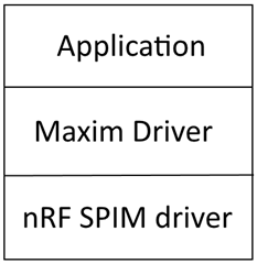
Good luck,
Håkon H.
Hello sir sorry for that,
may i know nrf SPIM driver means "spi_master_using_nrf_spi_mngr" example?
#include "nrfx_spim.h"
#include "app_util_platform.h"
#include "nrf_gpio.h"
#include "nrf_delay.h"
#include "boards.h"
#include "app_error.h"
#include <string.h>
#include "nrf_log.h"
#include "nrf_log_ctrl.h"
#include "nrf_log_default_backends.h"
#include "MAX30003.h"

#define NRFX_SPIM_SCK_PIN  3
#define NRFX_SPIM_MOSI_PIN 4
#define NRFX_SPIM_MISO_PIN 28
#define NRFX_SPIM_SS_PIN   29
#define NRFX_SPIM_DCX_PIN  30

#define SPI_INSTANCE  3                                           /**< SPI instance index. */

/* FOR MAX30003 ECG PART */
uint8_t SPI_RX_Buff[6];    /**< RX buffer. */
uint8_t SPI_TX_Buff[6];
static const uint8_t ECG_SIZE = sizeof(SPI_TX_Buff);        /**< Transfer length. */

//volatile char SPI_RX_Buff[5] ;
volatile char *SPI_RX_Buff_Ptr;
 	uint8_t A=0xFF;
  uint8_t A1=0x00;
int i=0;
unsigned long uintECGraw = 0;
signed long intECGraw=0;
uint8_t DataPacketHeader[20];
uint8_t data_len = 8;
signed long ecgdata;
unsigned long data;
char SPI_temp_32b;
char SPI_temp_Burst[100];

static const nrfx_spim_t spi = NRFX_SPIM_INSTANCE(SPI_INSTANCE);  /**< SPI instance. */

static volatile bool spi_xfer_done;  /**< Flag used to indicate that SPI instance completed the transfer. */

#define TEST_STRING "rohit"
static uint8_t       m_tx_buf[] = TEST_STRING;           /**< TX buffer. */
static uint8_t       m_rx_buf[sizeof(TEST_STRING) + 1];  /**< RX buffer. */
static const uint8_t m_length = sizeof(m_tx_buf);        /**< Transfer length. */

void timerIsr()                 //Its configuration is over
{
  	nrf_gpio_pin_toggle(NRF_FCLK_PIN);    // NRF_GPIO_PIN_MAP(1, 00) toggle Digital6 attached to FCLK  of MAX30003
}

void MAX30003_Reg_Write (unsigned char WRITE_ADDRESS, unsigned long data)
{
   nrf_gpio_pin_clear(NRFX_SPIM_SS_PIN);
   uint8_t  dataToSend = (WRITE_ADDRESS<<1) | WREG;
	 uint8_t temp_1 = (data>>16);  //number of register to wr
	 uint8_t temp_2 = (data>>8);
	 nrf_delay_ms(200);

	 nrfx_spim_xfer_desc_t xfer_desc = NRFX_SPIM_XFER_TRX(dataToSend, sizeof(dataToSend), SPI_RX_Buff, sizeof(dataToSend));
	 nrfx_spim_xfer_desc_t xfer_desc1= NRFX_SPIM_XFER_TRX(temp_1,  sizeof(temp_1),  SPI_RX_Buff, sizeof(temp_1));
   nrfx_spim_xfer_desc_t xfer_desc2= NRFX_SPIM_XFER_TRX(temp_2,  sizeof(temp_2),  SPI_RX_Buff, sizeof(temp_2));
   nrfx_spim_xfer_desc_t xfer_desc3= NRFX_SPIM_XFER_TRX(data,       sizeof(data),       SPI_RX_Buff,  sizeof(data));
	 nrf_delay_ms(200);
	 nrf_gpio_pin_set(NRFX_SPIM_SS_PIN);
}

void max30003_sw_reset(void)
{
  MAX30003_Reg_Write(SW_RST,0x000000);
  nrf_delay_ms(100);
}
void MAX30003_Reg_Read(uint8_t Reg_address)
{

    nrf_gpio_pin_clear(NRFX_SPIM_SS_PIN);
    SPI_TX_Buff[1] = (Reg_address<<1 ) | RREG;
    nrfx_spim_xfer_desc_t xfer_desc4 = NRFX_SPIM_XFER_TRX(SPI_TX_Buff[1], sizeof(SPI_TX_Buff[1]), SPI_RX_Buff, sizeof(SPI_TX_Buff[1]));

   for ( i = 0; i < 3; i++)
   {
         SPI_temp_32b[i]= NRFX_SPIM_XFER_TRX(A, sizeof(A), SPI_RX_Buff, sizeof(A));
   }

   nrf_gpio_pin_set(NRFX_SPIM_SS_PIN);
}
void spim_event_handler(nrfx_spim_evt_t const * p_event,
                       void *                  p_context)
{
    spi_xfer_done = true;
    NRF_LOG_INFO("Transfer completed.");
    if (m_rx_buf[0] != 0)
    {
        NRF_LOG_INFO(" Received:");
        NRF_LOG_HEXDUMP_INFO(m_rx_buf, strlen((const char *)m_rx_buf));
    }
}

int main(void)
{
    bsp_board_init(BSP_INIT_LEDS);

    APP_ERROR_CHECK(NRF_LOG_INIT(NULL));
    NRF_LOG_DEFAULT_BACKENDS_INIT();

    nrfx_spim_xfer_desc_t xfer_desc = NRFX_SPIM_XFER_TRX(m_tx_buf, m_length, m_rx_buf, m_length);

    nrfx_spim_config_t spi_config = NRFX_SPIM_DEFAULT_CONFIG;
    spi_config.frequency      = NRF_SPIM_FREQ_1M;
    spi_config.ss_pin         = NRFX_SPIM_SS_PIN;
    spi_config.miso_pin       = NRFX_SPIM_MISO_PIN;
    spi_config.mosi_pin       = NRFX_SPIM_MOSI_PIN;
    spi_config.sck_pin        = NRFX_SPIM_SCK_PIN;
    spi_config.dcx_pin        = NRFX_SPIM_DCX_PIN;
    spi_config.use_hw_ss      = true;
    spi_config.ss_active_high = false;
    APP_ERROR_CHECK(nrfx_spim_init(&spi, &spi_config, spim_event_handler, NULL));

    NRF_LOG_INFO("NRFX SPIM example started.");
     MAX30003_Reg_Read( 0x21);
	   MAX30003_Reg_Read( 0x25);

    while (1)
    {
        // Reset rx buffer and transfer done flag
        memset(m_rx_buf, 0, m_length);
        spi_xfer_done = false;

        APP_ERROR_CHECK(nrfx_spim_xfer_dcx(&spi, &xfer_desc, 0, 15));

        while (!spi_xfer_done)
        {
            __WFE();
        }

        NRF_LOG_FLUSH();

        bsp_board_led_invert(BSP_BOARD_LED_0);
        nrf_delay_ms(200);
    }
}
Hi Haakonsh,
Thanks for the reply and suggestions.
regards,
rohit
So what do you expect that code to do?
What does it actually do?
You should also scope the SPI communication with a digital logical analyzer
In other words, you need to examine the signals on the physical connections between the SPI Master (NRF52840-DK) and the SPI Slave (MAX30003 ECG Board) using a logic analyser, oscilloscope, or similar.
Have you done that?
What did you see?
Hi,
Thank you for your inputs, Now, I can read INFO (0x0F) register and receive some data in RX buffer but I don't know whether it is receiving correct data or not, can anyone help me how to verify the data.
FYR, attaching code
#define INFO ((uint8_t)0x0F)
int main(void)
{
MAX30003_Reg_Read(INFO);
bsp_board_init(BSP_INIT_LEDS);
APP_ERROR_CHECK(NRF_LOG_INIT(NULL));
NRF_LOG_DEFAULT_BACKENDS_INIT();
// nrfx_spim_xfer_desc_t xfer_desc = NRFX_SPIM_XFER_TRX(m_tx_buf, m_length, m_rx_buf, m_length);
nrfx_spim_config_t spi_config = NRFX_SPIM_DEFAULT_CONFIG;
spi_config.frequency = SPIM_FREQUENCY_FREQUENCY_K125;
spi_config.ss_pin = NRFX_SPIM_SS_PIN;
spi_config.miso_pin = NRFX_SPIM_MISO_PIN;
spi_config.mosi_pin = NRFX_SPIM_MOSI_PIN;
spi_config.sck_pin = NRFX_SPIM_SCK_PIN;
spi_config.dcx_pin = NRFX_SPIM_DCX_PIN;
spi_config.use_hw_ss = true;
spi_config.ss_active_high = false;
spi_config.mode = NRF_SPIM_MODE_2; // SCK active low, sample on trailing edge of clock
APP_ERROR_CHECK(nrfx_spim_init(&spi, &spi_config, spim_event_handler, NULL));
nrfx_spim_xfer_desc_t xfer_desc = NRFX_SPIM_XFER_TRX(SPI_TX_Buff, sizeof(SPI_TX_Buff), SPI_RX_Buff, sizeof(SPI_TX_Buff));
NRF_LOG_INFO("NRFX SPIM example started.");
while (1)
{
// Reset rx buffer and transfer done flag
memset(SPI_RX_Buff, 0, m_length);
spi_xfer_done = false;
APP_ERROR_CHECK(nrfx_spim_xfer_dcx(&spi, &xfer_desc, 0, 15));
while (!spi_xfer_done)
{
__WFE();
}
NRF_LOG_FLUSH();
bsp_board_led_invert(BSP_BOARD_LED_0);
nrf_delay_ms(200);
}
}
I want to know, how to analyze that received data is correct or not?
Please check the attached video?
Thanks,
Rohit
You've already forgotten how to properly post source code, then?
I want to know, how to analyze that received data is correct or not?
Really, that has nothing at all to do with Nordic - that's entirely up to you and the specifics of your application.
Again, you need to look to Maxim and the MAX30003 documentation for answers to such questions.
Their product page is here: https://www.maximintegrated.com/en/products/analog/data-converters/analog-front-end-ics/MAX30003.html
Look under 'Design Resources' - they have an evaluation kit , development platform, reference design, Tutorial, Application Note, and other resources ...
Note also their 'Support' link at the left-hand side of the page
