This post is older than 2 years and might not be relevant anymore
More Info: Consider searching for newer posts

nrf24l01+, pcb mifa antenna design

Hello guys,

I tried to design a pcb antenna for a nrf24l01+, since my company doesnt allow to buy cheap smd breakout board version from china anymore
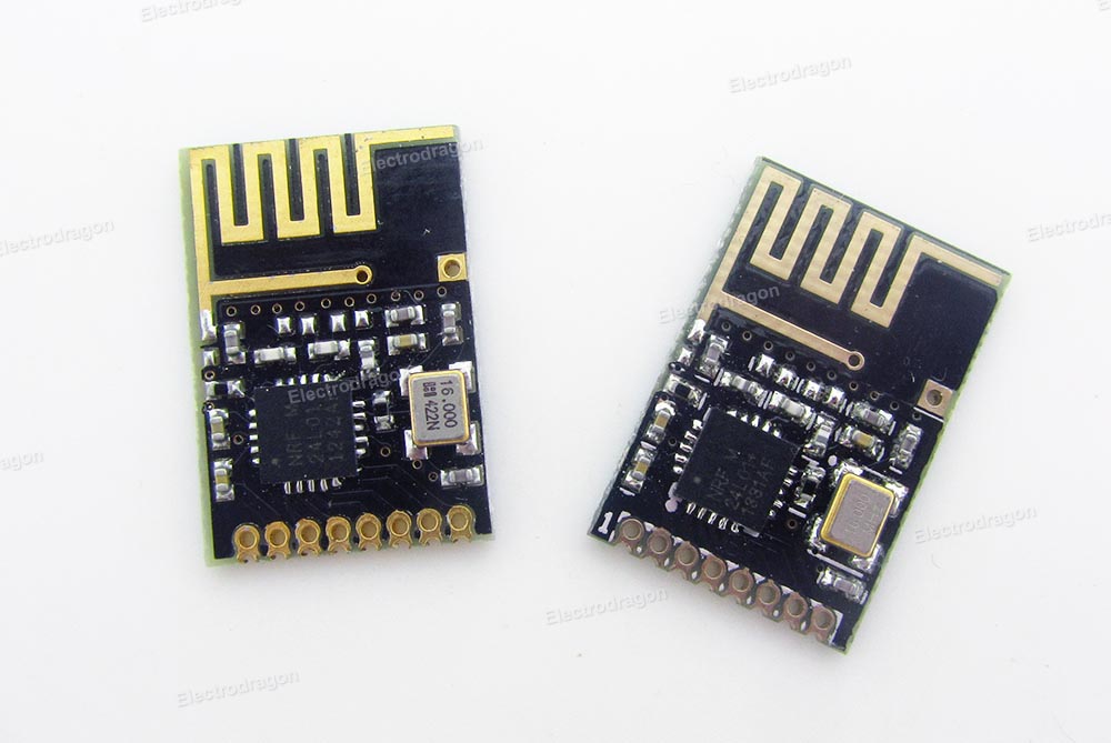
The pcb stats of the producer:

  • 2-layer FR4 1.55mm (61.023mil)  thickness, εr = 4.6
  • Copper thickness, 35μm (1.378mil)

What I used:

This results into following desgin block:


The antenna area is clear of any signals aswell as ground on top or bottom layer.

Since I have absolutly zero experience with RF antenna design I would like to have some opinions regarding my design.

Thanks so far,

Joe

  • Sorry for the late reply.  I saw your initial message then got swamped with work and it kind of got lost.

    Your impedance calculations are similar to AppCad. AppCad shows both designs closer to 45 ohms and to get it to 50 just make the gap width 0.14mm ( 5.5 mil). Actually above 5 mil will make your board cheaper since smaller than 5 mil is generally a more expensive process.

    It doesn't really matter if you do 4 layer or 2 layer.  You have room for the stripline so I would go for 2 layer since it is cheaper.  You should stitch your groundplane more. Most eda packages have a utility that will automatically stitch the entire board with vias. Unless you stitch it the analog portions of the chip won't operate correctly.

    You have the wrong footprint for the epad of nRF chip.

  • Okay, changed the wrong footprint, edited the gap, added alot stitches by hand since I dont know a feature in Eagle for that. Result below.

  • You need to turn off the thermals on the vias.  There should be a selection in your software that says something like "flood over vias". Only plated thru holes for leaded devices get thermals since this makes soldering easier.

    You can stitch under the crystal too.

    You forgot to put vias under the nRF. Not sure how many you can fit by looking at it.  But an X of 5 vias should probably be sufficient. Just make sure the annular rings are well inside of the edge of the pad. Then you let them flood with mask on the bottom layer and that effectively tents them.

    I normally also place a via directly behind or next to all shunt RF components.  The farther the ground via is away the worse the phase relationship of that part is to an ideal model.  If the ground is close by then the matching solution is a little more predictable.

  • More stitches and all without thermals, including crystal and nrf pad (managed to include 9 vias.)

  • Looks good.  The only thing left is the traces between RF components are rather narrow.  Now sometimes this is by design or sometimes it is just impossible to have characterized traces between the RF components or sometimes it just doesn't matter since the whole thing gets matched anyway.

    On the reference design the traces between the components on the nRF output match look to be about the same as the pad width.  This is a pretty standard practice that gives a less inductive trace while still meeting the trace/space spec for the board.

    Anyway, if you feel they are close to the reference designs for both the antenna and the nRF then run with it as is, otherwise I would fatten them up to closer to the width of the pad as long as you don't create spacing violations.

    After that make sure your DRC rules match your board vendors spec and run with it.  Looks fine to me.

Related