Hi,
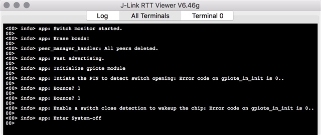
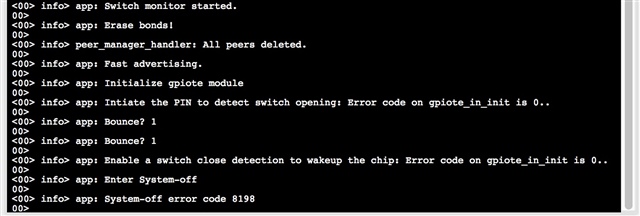
I am trying to merge working code that places the microcontroller in system_off when a switch connected to pin 16 is opened. It then wakes up the micro controller when switch is closed. The same pin is used to achieve this using GPIOTE. The challenge occurs when I merge this with the ble_proximity app. I can never get the chip to go to sleep when I remove the physical ground connector on PIN 16 and open the switch. However it worked perfectly when not merged with ble_proximity
I am effectively using method two neatly described here
I have found some useful information in the discussion below.
https://devzone.nordicsemi.com/f/nordic-q-a/37328/gpio-interrupt-with-ble-peripheral-code
It reveals that the conflict in the
buttons_leds_init(&erase_bonds);

function needs to be dealt with which I believe I have done.

So changes I have made are to file pca10040.h
//#define BUTTONS_NUMBER 4 - change to 3
#define BUTTONS_NUMBER 3

so only the first three buttons are initialised effectively liberating pin 16

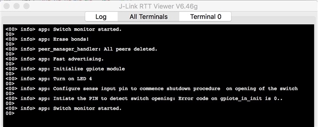
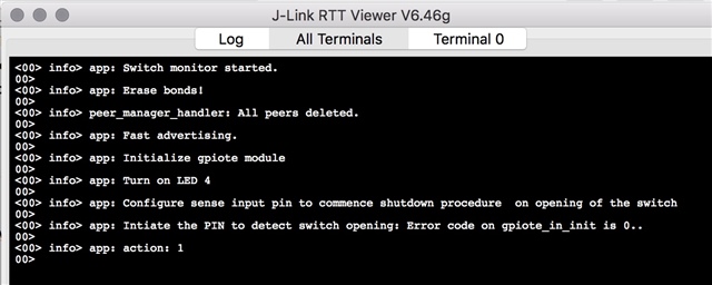
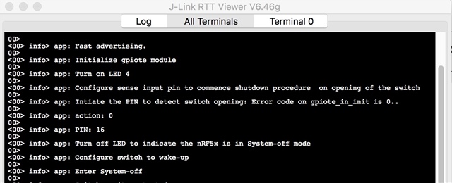
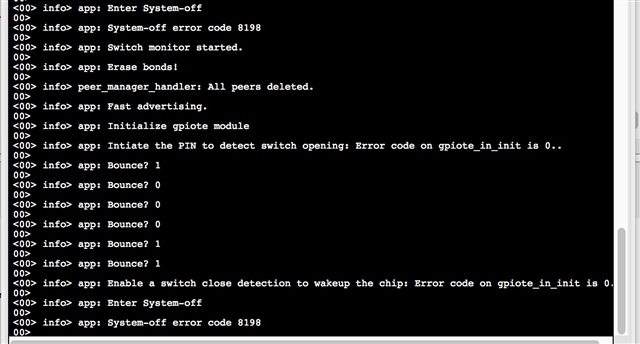
My code is as per below and there must be something incorrect with the configuration of pin 16 as the in_pin_handler is never called.
#define SWITCH_PIN   BUTTON_4
#define PIN_OUT      LED_4
/**
 * @brief Interrupt handler for wakeup pin
 */

void in_pin_handler(nrf_drv_gpiote_pin_t pin, nrf_gpiote_polarity_t action)
{
		ret_code_t err_code;
              NRF_LOG_INFO("ON WAKEUP SWITCH PIN state is: %d..", nrf_gpio_pin_read(pin));

		if (pin == SWITCH_PIN)
		{
				//Turn off LED to indicate the nRF5x is in System-off mode
                NRF_LOG_INFO("Turn off LED to indicate the nRF5x is in System-off mode");
		nrf_drv_gpiote_out_set(PIN_OUT);

				//Disable power-down button to prevent System-off wakeup
                NRF_LOG_INFO("Disable power-down button to prevent System-off wakeup");
		nrf_drv_gpiote_in_uninit(SWITCH_PIN);
                nrf_drv_gpiote_in_event_disable(SWITCH_PIN);

				//Configure wake-up button
                NRF_LOG_INFO("Configure switch to wake-up");
		nrf_drv_gpiote_in_config_t in_config = GPIOTE_CONFIG_IN_SENSE_HITOLO(false);    //Configure to generate interrupt and wakeup on pin signal low. "false" means that gpiote will use the PORT event, which is low power, i.e. does not add any noticable current consumption (<<1uA). Setting this to "true" will make the gpiote module use GPIOTE->IN events which add ~8uA for nRF52 and ~1mA for nRF51.
		in_config.pull = NRF_GPIO_PIN_PULLUP;                                           										 //Configure pullup for input pin to prevent it from floting. Pin is pulled down when button is pressed on nRF5x-DK boards, see figure two in http://infocenter.nordicsemi.com/topic/com.nordic.infocenter.nrf52/dita/nrf52/development/dev_kit_v1.1.0/hw_btns_leds.html?cp=2_0_0_1_4
		err_code = nrf_drv_gpiote_in_init(SWITCH_PIN, &in_config, NULL);                //Initialize the wake-up pin
		APP_ERROR_CHECK(err_code);                                                      											//Check error code returned
		nrf_drv_gpiote_in_event_enable(SWITCH_PIN, true);                            	//Enable event and interrupt for the wakeup pin

				//Enter System-off
                NRF_LOG_INFO("Enter System-off");
		NRF_POWER->SYSTEMOFF = 1;
                      while(1){
								//This has been put in here to  prevent spurious calls whilst in debug mode
                               }
		}
}


/**
 * @brief Function for configuring: PIN_IN_POWER_DOWN pin (BUTTON_1) to enter System-off,
 * PIN_IN_WAKE_UP pin (BUTTON_2) to wake up from System-off, and PIN_OUT pin for LED_1 output
 */

static void gpio_init(void)
{
    ret_code_t err_code;

	//Initialize gpiote module
    NRF_LOG_INFO("Initialize gpiote module");
    if(!nrf_drv_gpiote_is_init())
        {
        err_code = nrf_drv_gpiote_init();
        APP_ERROR_CHECK(err_code);
        }
    NRF_LOG_INFO("Error is: %d..", err_code);

	//Initialize output pin
    NRF_LOG_INFO("Turn on LED 4");
    nrf_drv_gpiote_out_clear(PIN_OUT);                                               	//Turn on LED to indicate that nRF5x is not in System-off mode

	//Configure sense input pin to enable wakeup and interrupt on buckle closure 1-> 0 as high to ground
    nrf_drv_gpiote_in_uninit(SWITCH_PIN);
    nrf_drv_gpiote_in_event_disable(SWITCH_PIN);
    NRF_LOG_INFO("Configure sense input pin to commence shutdown procedure  on opening of the switch");
    nrf_drv_gpiote_in_config_t in_config = GPIOTE_CONFIG_IN_SENSE_LOTOHI(false);                                //Configure to generate interrupt and go to system_off on pin signal high. "false" means that gpiote will use the PORT event, which is low power, i.e. does not add any noticable current consumption (<<1uA). Setting this to "true" will make the gpiote module use GPIOTE->IN events which add ~8uA for nRF52 and ~1mA for nRF51.
    in_config.pull = NRF_GPIO_PIN_PULLUP;                                                                       //Configure pullup for input pin to prevent it from floating. Pin is pulled down when button is pressed on nRF5x-DK boards, see figure two in http://infocenter.nordicsemi.com/topic/com.nordic.infocenter.nrf52/dita/nrf52/development/dev_kit_v1.1.0/hw_btns_leds.html?cp=2_0_0_1_4
    err_code = nrf_drv_gpiote_in_init(SWITCH_PIN, &in_config, in_pin_handler);  				//Initialize the pin with interrupt handler in_pin_handler
    NRF_LOG_INFO("Error is: %d..", err_code);
    APP_ERROR_CHECK(err_code);                                                          			//Check potential error
    nrf_drv_gpiote_in_event_enable(SWITCH_PIN, true);                            				//Enable event and interrupt for the wakeup pin
    NRF_LOG_INFO("Got to here");
    NRF_LOG_INFO("SWITCH PIN state is: %d..", nrf_gpio_pin_read(SWITCH_PIN));
}


/**@brief Function for application main entry.
 */
int main(void)
{
    bool erase_bonds;
    // Initialize.
    log_init();
    timers_init();
    buttons_leds_init(&erase_bonds);
    power_management_init();
    ble_stack_init();
    adc_configure();
    gap_params_init();
    gatt_init();
    advertising_init();
    db_discovery_init();
    services_init();
    conn_params_init();
    peer_manager_init();

    // Start execution.
    NRF_LOG_INFO("Proximity example started.");
    advertising_start(erase_bonds);
    tx_power_set();
    gpio_init();

    // Enter main loop.
    for (;;)
    {
       // idle_state_handle();
        NRF_LOG_INFO("Got to here in main loop");
        NRF_LOG_INFO("SWITCH PIN state is: %d..", nrf_gpio_pin_read(SWITCH_PIN));
        nrf_delay_ms(5000);

    }
}


Any help greatly appreciated as to where I am getting this wrong.

Best,
DW


